P.3.42
SEL-411L Relay Protection Manual Date Code 20151029
Protection Functions
87L Differential Elements
for 87LGA. If the advanced settings are disabled, setting 87LGA sets
87LGAS to 1.2 • 87LGA, but no greater than the maximum setting limit of
270 degrees.
Select a blocking angle setting to ensure security against measurement errors
in current angles that might result typically from CT saturation or
synchronization errors resulting from channel asymmetry.
External fault detection logic in the relay allows you to be liberal in your
choice of a blocking angle setting.
When you use channels that are guaranteed to be symmetrical (for example,
direct fiber), channel asymmetry is not a concern and you can make this
setting more sensitive. Also, by applying external time-based synchronization
to asymmetrical channels, you reduce the danger of synchronization errors
and can use lower blocking angle values. Note that the time fallback logic that
responds to the loss or degradation of the time sources you use will force the
extended security settings. You may therefore set the blocking angle setting in
the extended security mode, 87LGAS, conservatively, while setting the
regular security blocking angle setting, 87LGA, to be more sensitive.
Note that the zero-sequence network is typically very homogeneous; the
Alpha Plane angle under internal faults is very close to zero. Therefore, a
conservative value for the 87LGA or 87LGAS setting typically does not
impact dependability of the 87LG element.
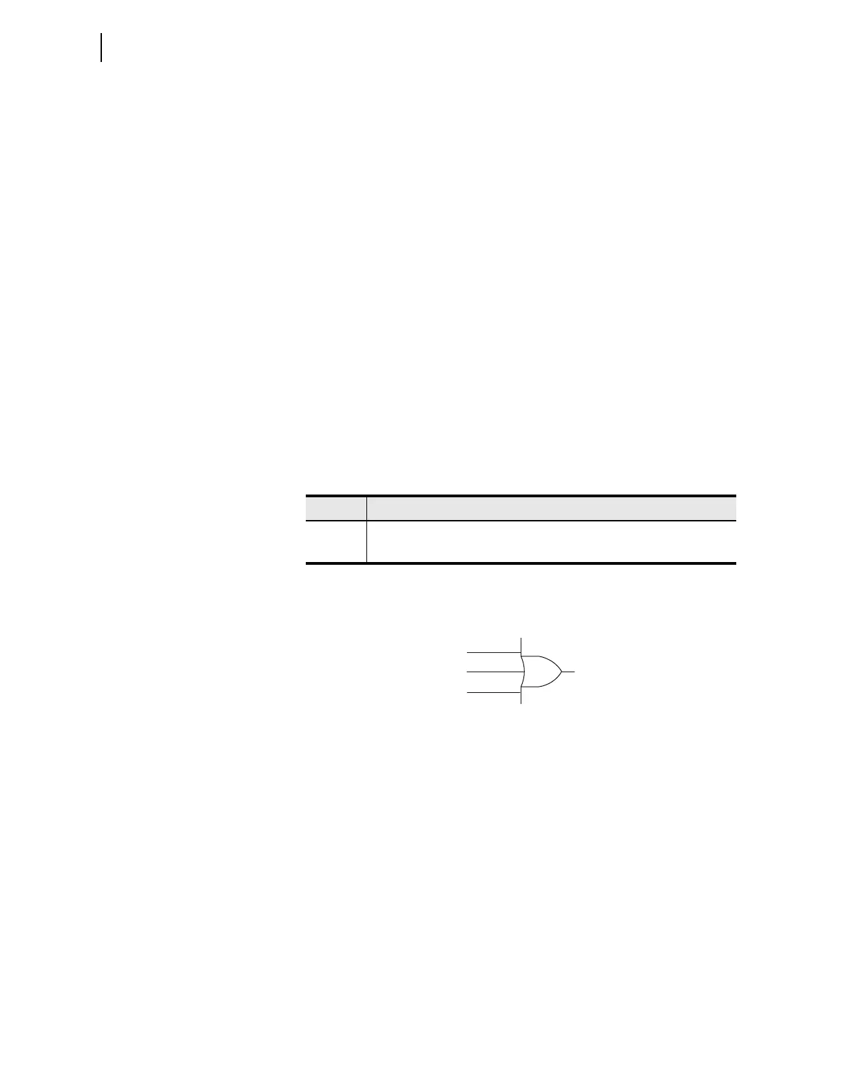
As Figure 3.24 shows, the locally generated current-based 87L Relay Word
bits are ORed for your convenience and are available as the 87OP Relay Word
bit.
Figure 3.24 87OP Logic
Time-Overcurrent Differential Protection
The relay allows the protection of lines with tapped loads without the current
measurement at the tap that normally defines the differential zone. It is
possible to make such partial line current differential applications selective,
particularly if the tapped and unmeasured load are connected through a step-
down power transformer. The transformer impedance reduces line differential
currents for faults within the tapped load network (network fed from the low
side of the transformer), providing a better coordination margin.
For this application, you must set the 87L elements so that they do not respond
to faults in the tapped load network. You typically accomplish this by
increasing the pickup threshold or by using distance supervision for the 87L
trips.
Table 3.11 87LG Zero-Sequence Differential Element Relay Word Bits
Name Description
87LG Zero-sequence differential element operated
87L50G Overcurrent supervision of the zero-sequence differential element picked up
Relay Word Bit
87OP
Relay Word Bit
87LP
87LQ
87LG