P.3.17
Date Code 20151029 Protection Manual SEL-411L Relay
Protection Functions
87L Theory of Operation
Following the Dedicated Relay Approach While the Backup Protection Uses a
Single 87L Relay (c)
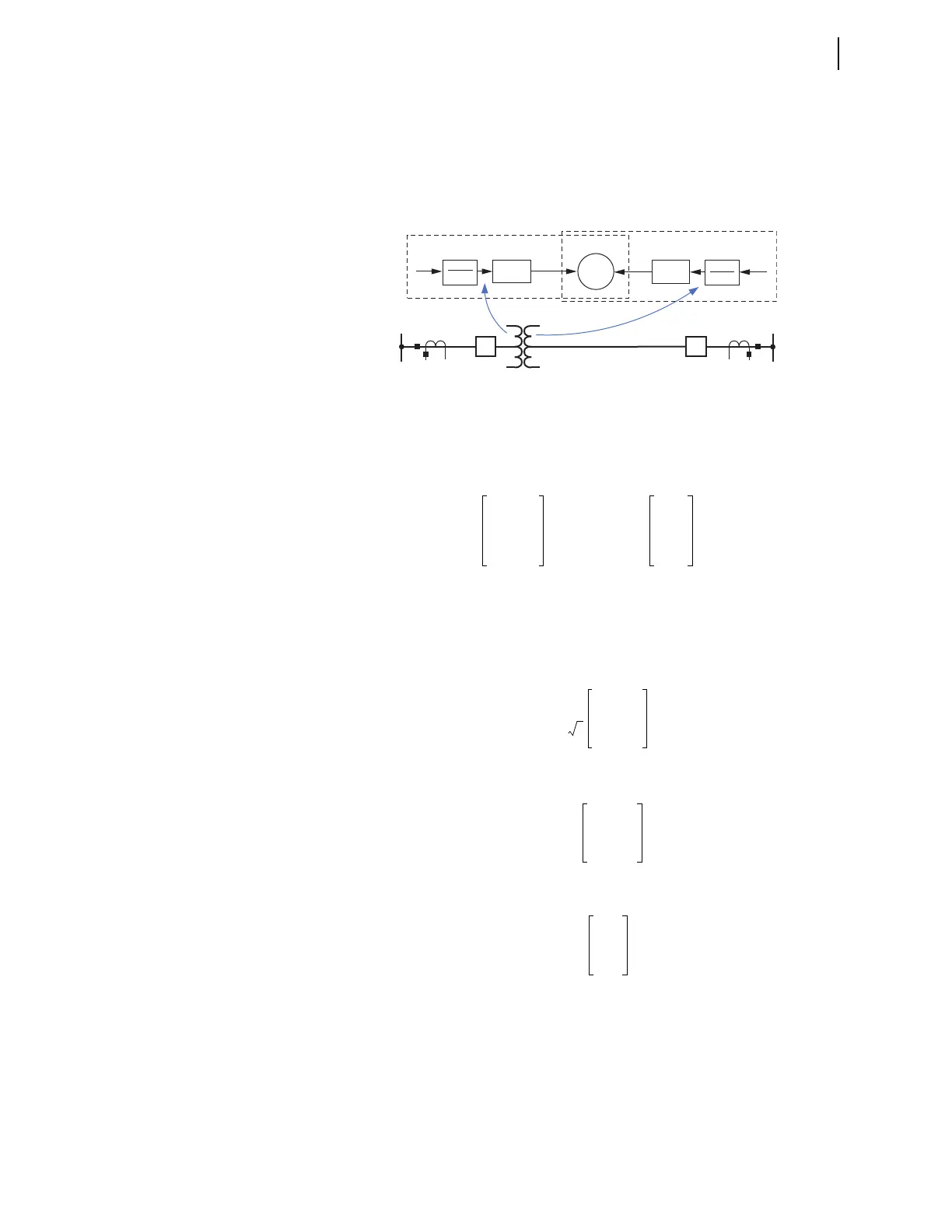
The relay performs proper compensation of measured currents in the local
relay prior to transmitting the current data (see Figure 3.11), keeping
remaining signal processing and algorithms intact after adjustment of the
measured currents to account for the in-line transformer.
Figure 3.11 Compensation for In-Line Transformers is Performed at Early
Stages of Signal Processing, Allowing the Rest of the Algorithm to Remain
Unchanged
We can use matrix notation to write the compensation equations in the
following general form:
Equation 3.22
where the 3x3 matrix [T] reflects the winding connection associated with a
given CT (we assume all CTs to be connected in wye).
For example, for a wye-connected winding of a power transformer, you might
use the following:
Equation 3.23
while a power zigzag winding may require:
Equation 3.24
or a delta-connected winding may call for:
Equation 3.25
Please refer to 87L Differential Applications With In-Line Transformers for a
complete list of all supported compensating matrices and application
guidelines on selecting them.
Note that the relay allows one transformer winding per CT input of the relay.
For example, a dual CT input relay can be connected to measure two different
windings of an in-line transformer. Each winding can have different
connections for which a different compensating matrix setting is necessary.
CT1 CT2
87
L+T
i
CT1
Relay 1
Relay 2
[T
1
]
1
TAP
1
i
CT2
[T
2
]
1
TAP
2
i
XFMR A
i
XFMR B
i
XFMR C
1
TAP
------------ T
i
CT A
i
CT B
i
CT C
• • =
T
1
3
-------
1–10
01–1
–1 0 1
=
T
1
3
---
2–1–1
–12–1
–1 –1 2
=