P.3.13
Date Code 20151029 Protection Manual SEL-411L Relay
Protection Functions
87L Theory of Operation
stabilizing effect. This increase in the restraining term moves
the operating points on the generalized Alpha Plane toward the
ideal blocking point (1–180°), increasing security of the
87LQ and 87LG elements. Refer to 87LP Phase Differential
Elements for more information about the 87L logic.
Note that the EFD Relay Word bit does not block the 87L elements (you have
the option of doing this blocking via SEL
OGIC control equations). The relay
uses this design solution to maintain dependability for evolving external to
internal faults and for internal faults following a cleared external fault within
the period that the dropout timers maintain the EFD bit.
External Fault Detection Logic describes the EFD logic in detail.
Line Charging Current
Compensation
The relay compensates for line charging current by estimating an
instantaneous value of the total line charging current on a per-phase basis and
subtracting this value from the measured differential current. The relay uses
instantaneous values of the line voltage and user-provided susceptance of the
line, both positive- and zero-sequence, to calculate charging current in real
time on a sample-by-sample basis.
This compensation method is accurate under steady state and transient
conditions; the latter including external faults, internal faults, switching
events, line energization even with uneven breaker pole operation, etc.
Compensating the phase currents automatically removes the charging current
from the sequence currents and improves not only the 87LP element, but the
87LQ and 87LG elements as well.
Each relay terminal of a given 87L scheme with access to voltage uses the
lump parameter model of the transmission line and the local terminal voltage
to calculate total charging current.
Equation 3.13
Subsequently, the relay subtracts a portion of the total charging current
proportional to the number of compensating terminals from the local phase
current (from the “partial differential” term). For example, with two relays
compensating for the charging current, each subtracts half of the total
charging current; with three relays compensating, each subtracts one third of
the total charging current. Assume compensation by two relays (1 and 2).
Each will augment the local current as follows.
Equation 3.14
Equation 3.15
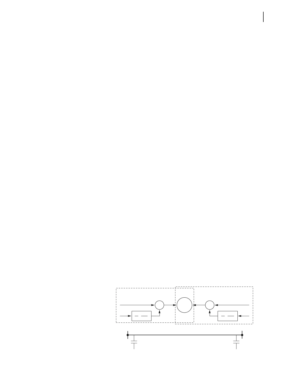
Figure 3.7 Illustration of Signal Processing for Line Charging Current
Compensation
i
CHARGE
C
LINE
dv
dt
------• =
i
LOC1
i
MEASURED1
0.5 C
LINE
dv
1
dt
--------• • –=
i
LOC2
i
MEASURED2
0.5 C
LINE
dv
2
dt
--------• • –=
v
1
v
1
v
2
v
2
dv
1
dt
C
1
2
dv
1
dt
C
1
2
Σ
–
Σ
–
87L
i
MEASURED1
i
MEASURED2
Relay 1
Relay 2
i
LOC1
i
LOC2