P.11.33
Date Code 20151029 Protection Manual SEL-411L Relay
Testing and Troubleshooting
Checking Relay Operation
f. If you need to change these settings, set E32 to Y.
Table 11.10 shows the calculations.
See Ground Directional Element on page P.3.142 for
details on these relay calculations.
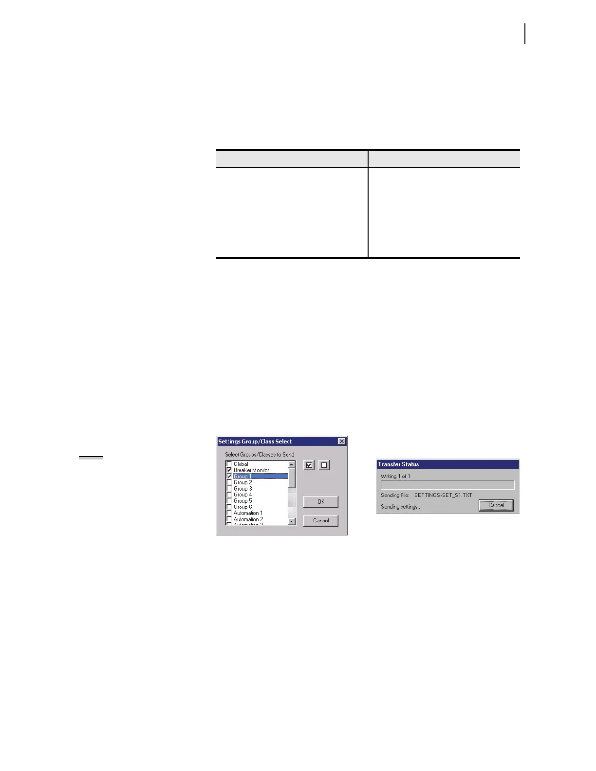
Step 3. Upload the new settings to the relay.
a. Click File > Send.
ACSELERATOR QuickSet prompts you for the settings
class you want to send to the relay, as shown in the
Group Select dialog box in Figure 11.16.
b. Click the check box for Group 1 and for Breaker
Monitor.
c. Click OK.
d.
ACSELERATOR QuickSet responds with a Transfer
Status dialog box as in Figure 11.16.
If you see no error message, the new settings are loaded
in the relay.
Figure 11.16 Uploading Group 1 and Breaker Monitor Settings to the Relay
Step 4. Display the F32Q and R32Q Relay Word bits on the front-
panel LCD screen.
a. Access the front-panel LCD
MAIN MENU.
b. Highlight
RELAY ELEMENTS and press ENT.
You will see a
RELAY ELEMENTS screen with SEARCH
highlighted at the bottom of the screen.
c. Press ENT to go to the
ELEMENT SEARCH submenu of
Figure 11.14.
d. Enter characters in the text input field using the
navigation keys.
e. Highlight
F and press ENT to enter the F character.
Table 11.10 Negative-Sequence Directional Element Settings AUTO
Calculations
Setting Calculation
50FP 0.12 • I
NOM
50RP 0.08 • I
NOM
Z2F 0.5 • Z1MAG
Z2R Z2F + 1 / (2 • I
NOM
)
a2 0.1
k2 0.2
NOTE: The Relay Editor dialog
boxes shown in Figure 11.16 are for
the -1 relay. The -0 relay dialog
boxes do not contain Automation
2–10 setting instances.