P.12.23
Date Code 20151029 Protection Manual SEL-411L Relay
Bay Control
Bay Control Front-Panel Operations
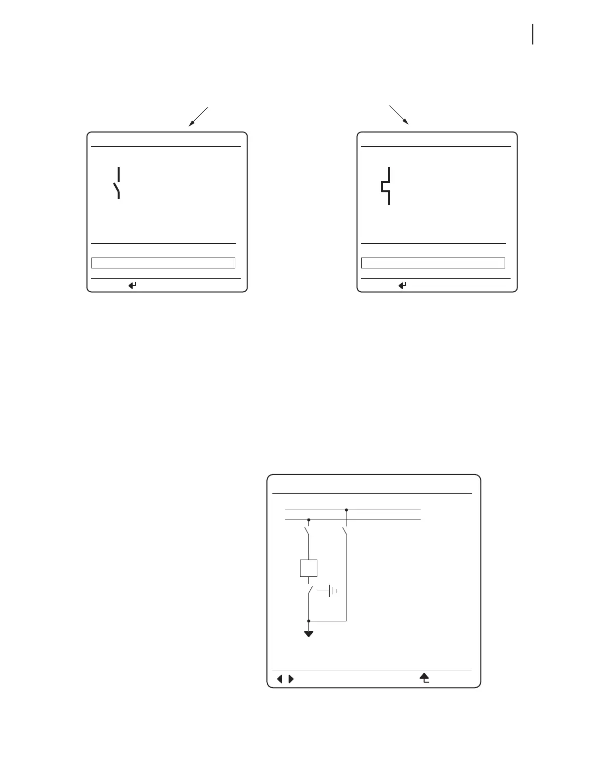
Figure 12.13 HMI Disconnect Operation Completed
Three-Position
Disconnect State
Representation and
Operations From the
Front Panel
A three-position disconnect switch consists of two standard disconnects that
operate together to form a three-position disconnect. All logic diagrams of the
standard disconnect apply to the three-position disconnect, including all
settings and Relay Word bits associated with the two individual disconnects.
The three-position disconnect has two labels, one for the in-line branch and
one for the ground (perpendicular) branch. In the example shown in
Figure 12.14, the three-position disconnect is made up of Disconnect SW3
and Disconnect SW4. As with the standard disconnect, be sure to correlate the
disconnect wiring and settings with the disconnects assigned to the three-
position disconnect image on the one-line diagram.
Figure 12.14 Bay Control One-Line Diagram With Three-Position Disconnect
Open
(b) Disconnect Control Screen
(a) Disconnect Control Screen
BAYNAME
OPEN DISCONNECT
CLOSE DISCONNECT
STATUS
UNKNOWN
<DmCTLN>
PRESS TO ACTIVATE
BAYNAME
OPEN DISCONNECT
CLOSE DISCONNECT
CLOSE
<DmCTLN>
PRESS TO ACTIVATE
89AL1 or
89CIMD1
asserted
89CL1
asserted
BAYNAME
ESCNAVIG
I:9999A
V:99999kV
P:99999MW
Q:99999MV
BUS 1
SW3
SW4
BK1
SW1 SW2
BUS 2