P.3.265
Date Code 20151029 Protection Manual SEL-411L Relay
Protection Functions
87L Communication and Timing
supplied in a relay is isolated from the chassis to 1500 V rms. Therefore the
signal common is also isolated from the chassis, preventing ground loops. To
preserve that isolation, ground the cable shield only at the point.
A clock signal is employed to control the transmission and reception of data.
There are two clock edges (rising and falling) for each clock cycle. Depending
on the particular interface equipment, data may be read either on the rising or
falling clock edge.
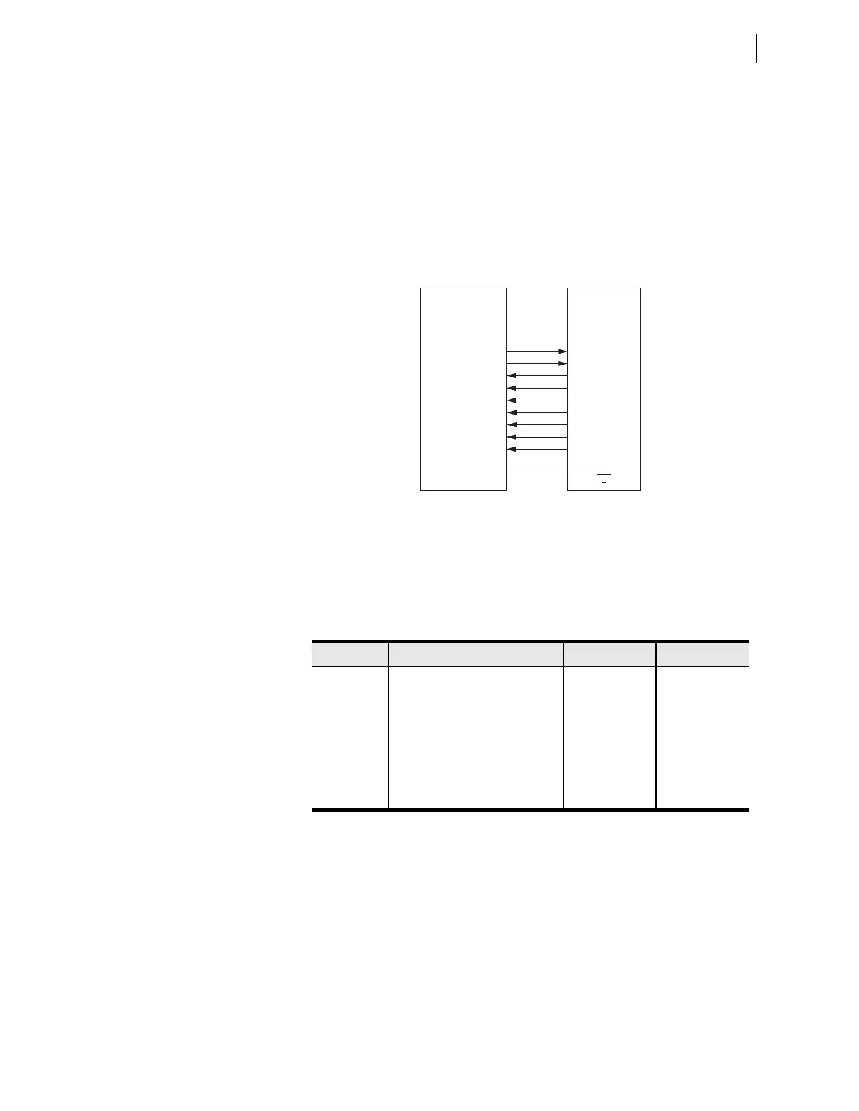
The DB-25 connector pinout on the relay is shown in Figure 3.178, and is per
EIA-530. Figure 3.178 also shows the direction of signal flow for an EIA-422
interface.
Figure 3.178 EIA-422 Typical Connection
Refer to Table 3.136 for the EIA-422 cable appropriate to your application.
All of the cables shown in Table 3.136 connect the shield at the multiplexer
end only.
EIA-422 Clock Settings
The receive clock polarity settings indicate the clock edge on which the data
should change. Set 87RXCE1 to R if the multiplexer is set to change data on
the rising edge of the receive clock (rising edge of signal RXCB on DB-25 pin
9, falling edge of signal RXCA on DB-25 pin 17).
The transmit clock polarity clock settings indicate clock sampling edges. For
example, set 87TXCE1 = R if the multiplexer is set to sample transmit data on
the rising edge of the transmit clock (rising edge of signal TXCB on DB-25
pin 12, falling edge of signal TXCA on DB-25 pin 15).
TXDA
TXDB
RXDA
RXDB
RXCA
RXCB
TXCA
TXCB
COMMON
SHIELD*
2
14
3
16
17
9
15
12
7
Relay
CH1/2
DB25 pin male
MUX
or Interface
Convertor
Table 3.135 EIA-422 Clock Settings
Setting Description Range Default
87RXCE1 Channel 1 EIA-422 receive clock
edge
R (rising),
F (falling)
R
87TXCE1 Channel 1 EIA-422 transmit clock
edge
R (rising),
F (falling)
R
87RXCE2 Channel 2 EIA-422 receive clock
edge
R (rising),
F (falling)
R
87TXCE2 Channel 2 EIA-422 transmit clock
edge
R (rising),
F (falling)
R