P.9.29
Date Code 20151029 Protection Manual SEL-411L Relay
Monitoring and Metering
Metering
EXAMPLE 9.11 Calculating Exact Error Coefficients
Consider the case of a 5 A relay during normal operating conditions.
The secondary current in the CT is 1.0 A for nominal system
operation. Noting that this current is greater than 10 percent of I
NOM
(1 A > 0.5 A), calculate the error coefficient:
Equation 9.7
Figure 9.16 represents the calculated accuracy range. The error is
very small, indicating that the relay measures normal operating
currents accurately.
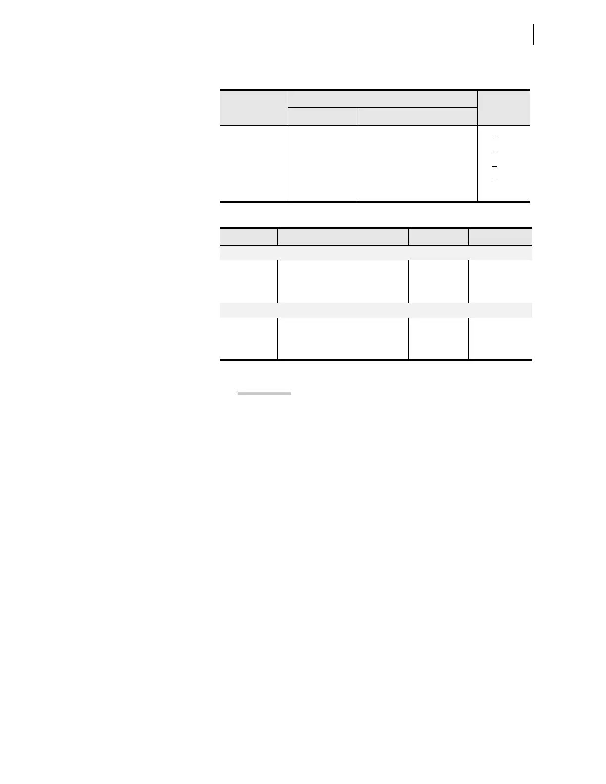
Table 9.15 Instantaneous Metering Accuracy—Voltages, Currents, and
Frequency
Quantity
Magnitude Accuracy
Phase
Accuracy
Range Specification
V
, V
33.5 – 200 V
L–N
± 0.1% +0.05°
3V0, V1, 3V2 33.5 – 200 V
L–N
± 0.15% +0.10°
I
(0.5 – 3)• I
NOM
±0.2% ± (0.8 mA) • I
NOM
+0.20°
3I0, I1, 3I2 (0.5 – 3)
• I
NOM
± 0.3% ± (1.0 mA) • I
NOM
+0.30°
f 40–65 Hz ±0.01 Hz
Table 9.16 Instantaneous Metering Accuracy—Power
Quantity Description Power Factor Accuracy (%)
a
a
Power accuracy is valid for applied currents in the range (0.1–1.2) • I
NOM
, and applied voltages
from 33.5–75 V.
At 0.1 • I
NOM
3P Three-phase rms real power Unity
–0.5 or +0.5
±0.40
±0.70
3Q
1
Reactive power –0.5 or +0.5 ±0.50
At 1.0 • I
NOM
3P Three-phase fundamental real power Unity
–0.5 or +0.5
±0.40
±0.40
3Q
1
Reactive power –0.5 or +0.5 ±0.40
error 0.2% 1.0 A• 0.8 mA I
NOM
• =
0.002 1.0 A• 0.0008 A 5• =
0.002A 0.004A=
+0.002 A to +0.006 A=
and
–0.006 A to –0.002 A=