P.2.28
SEL-411L Relay Protection Manual Date Code 20151029
Installation
Connection
Port 5A and 5B are for 87L over Ethernet communications, Port 5C and 5D are for all other Ethernet communications.
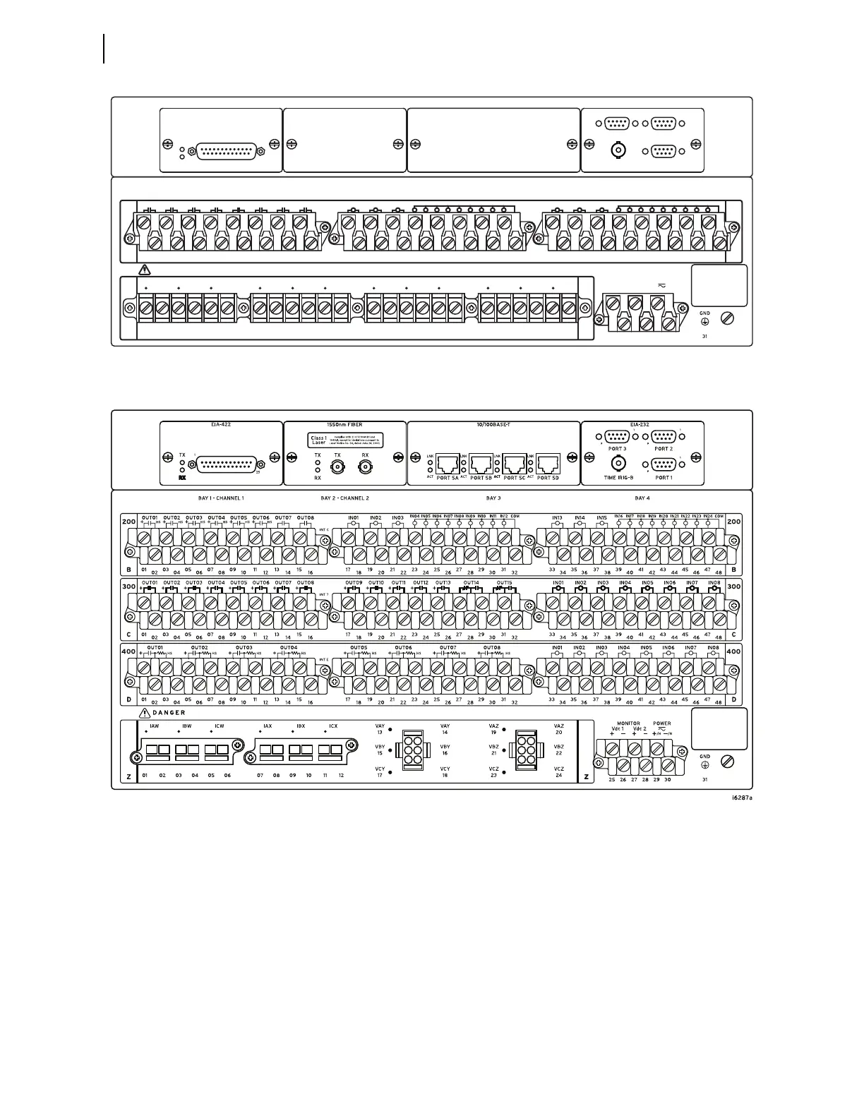
Figure 2.25 4U Rear, Main Board With EIA-422 Serial Communications Card in Bay 1, High-Speed INTC (200
Slot) Interface Board
Figure 2.26 6U Rear, Main Board With EIA-422 Serial Communications Card in Bay 1, 1550 nm Fiber-Optic
Communications Card in Bay 2, Four 10/100BASE-T Port Ethernet Card in Bay 3, High-Speed INTC (200 Slot)
Interface Board, INT 7 (300 Slot) Interface Board, INTE (400 Slot) Interface Board, Connectorized Terminal
Blocks for Current and Voltage Inputs
Rear-Panel Symbols
There are important safety symbols on the rear of the relay (see Figure 2.27).
Observe proper safety precautions when you connect the relay at terminals
marked by these symbols. In particular, the danger symbol located on the rear
panel corresponds to the following: Contact with instrument terminals can
cause electrical shock that can result in injury or death. Be careful to limit
access to these terminals.
IN01 IN02 IN03
IN04 IN05 IN06 IN07 IN08 IN09 IN10 IN11 IN12 COM
IN13 IN14 IN15
IN16 IN17 IN18 IN19 IN20 IN21 IN22 IN23 IN24 COM
OUT01 OUT02 OUT03 OUT04 OUT05 OUT06 OUT07 OUT08
18
17 2119
20 22
23
26
25
24
27
28 30
29 31
32 34
33 3735
36 38
39
42
41
40
43
44 46
45 47
4802
01
04
03 05
06
09
08
07
10
11
1412
13 15
16
200
B
200
B
INT C 196–1504
HS
+
HS
+
HS
+
HS
+
HS
+
HS
+
HS
+
IAW IBW ICW IAX IBX ICX VAY VBY VCY VAZ VBZ VCZ
26 28 3025 27 29
01 02 03 04 05 06 07 08 09 10 11 12 13 14 15 16 17 18 19 20 21 22 23 24
DANGER
Z Z
MONITOR POWER
Vdc 1
+—
Vdc 2
+—
/H /N
+—
BAY 2 - CHANNEL 2 BAY 3 BAY 4BAY 1 - CHANNEL 1
PORT 2PORT 3
EIA-232
1
9
1
9
1
9
1
9
1
9
1
9
PORT 1TIME IRIG–B
EIA-422
TX
1
25
RX