P.12.30
SEL-411L Relay Protection Manual Date Code 20151029
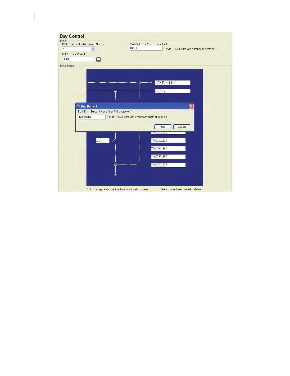
Bay Control
ACSELERATOR QuickSet SEL-5030 Software Bay Control Screens
Figure 12.20 Busbar Label
Disconnect
Assignments
Next to each disconnect is a box with its default HMI name. Click in the box
next to the D1 disconnect (to set Disconnect 1), the form shown in
Figure 12.21 appears, showing all the D1 disconnect settings.
Notice that the position of each disconnect switch is fixed in a certain screen.
The left-most top disconnect is always D1 (Disconnect 1). In this example, the
one on the right side of Disconnect 1 is D2 (Disconnect 2) and the one at the
bottom is D3 (Disconnect 3).