P.3.95
Date Code 20151029 Protection Manual SEL-411L Relay
Protection Functions
87L Differential Elements
Charging Current Compensation Settings With In-Line Transformers
The relay compensates the 87L function for line charging current in
applications with in-line transformers. This feature is beneficial when
protecting cables and connected transformers. Long high-voltage overhead
lines are rarely protected using a combined zone for line and transformer
protection.
Refer to Charging Current Compensation Logic for general information on
configuring the line charging current compensation feature of the 87L
function. This section only describes settings that are specific to applications
with in-line transformers, and provides a numerical example for better
illustration of the setting rules.
In applications with in-line transformers, the voltage source the relay uses to
calculate the charging current in real time may be located on the line side of
the transformer, or on one of the transformer windings not directly connected
to the power line. In order to allow the relay to use the voltage source properly,
set the voltage level of the power line and the vector group compensation
matrix.
The 87VTCC setting specifies the voltage level of the power line so that the
relay can scale the calculated charging current properly taking into account
the nominal voltage level of the connected VT. Note that the VT is not
necessarily installed on the power line, thus the VT can potentially measure a
different voltage level.
The 87CTCCC vector group compensation matrix setting informs the relay
about the required compensation for the calculated charging current given the
location of the voltage source and the power line with respect to the vector
group of the power transformer windings.
Detailed Description of Settings
87VTCC
This setting specifies the nominal phase-to-phase power line voltage level, in
kV. This value is set identically for all relays of a given 87L scheme. The relay
uses this value to calculate the internal tap values for the calculated line
charging current as follows.
Equation 3.38
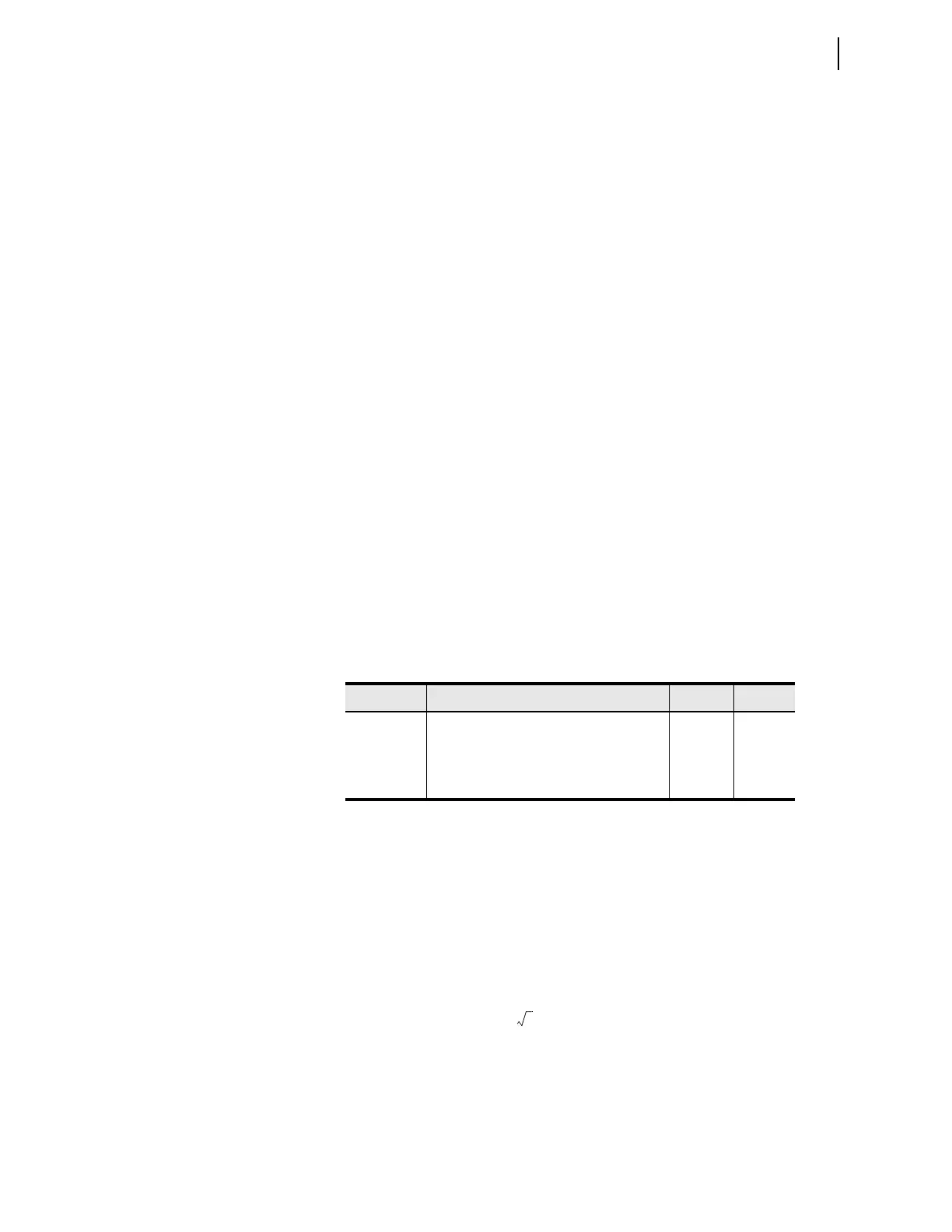
Table 3.38 87L Applications With In-Line Transformers and Charging
Current Compensation Settings
Setting Description Range Default
87VTCC Line-to-line voltage of the power line (kV) 1–1000 230
87CTCCC Vector group compensation matrix for the
line-charging currents
0–12 0
87TAPCC
a
a
Read-only setting.
CT tap for the calculated charging current 0.1–50 5
where:
PTR is the ratio of the potential transformer,
VNOM is the nominal secondary voltage of the potential
transformer,
87TAPCC
87MVA PTR 87LINEV VNOM 87LINEV
387VTCC
2
CTR_LOC
-----------------------------------------------------------------------------------------------------------------------------=