P.3.174
SEL-411L Relay Protection Manual Date Code 20151029
Protection Functions
Out-of-Step Logic (Zero Settings)
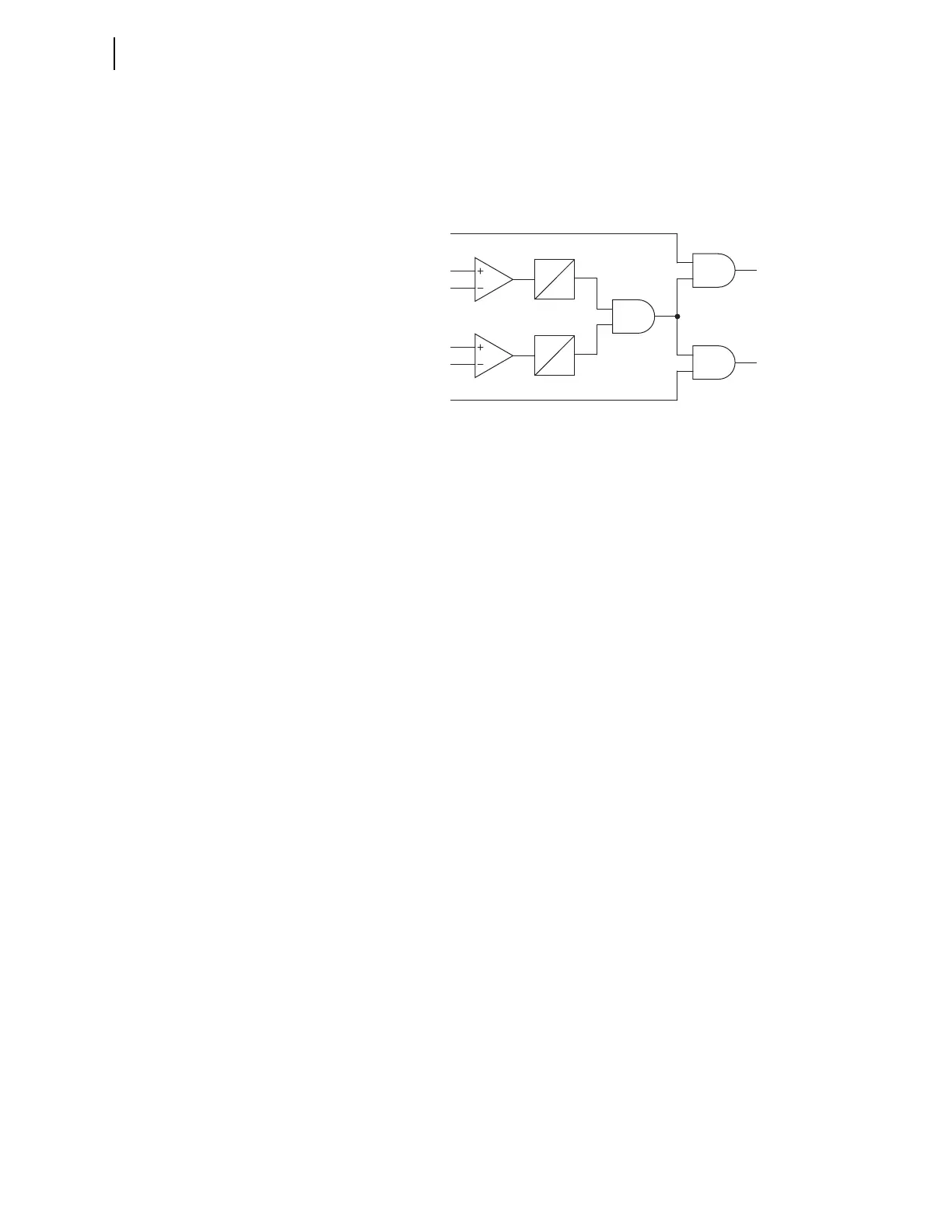
To detect phase-to-phase faults, the relay uses a directional overcurrent
element, 67QUBF, based on a negative-sequence directional element, 32QF,
as shown in Figure 3.116. 3IA2LFM is the negative-sequence current that the
relay measures. If 3IA2LFM exceeds a reference value (a2 • 3 • IA1LFM),
Timer 1 starts. If Timer 1 expires and the flow of negative-sequence current is
in the forward direction (32QF asserted), then 67QUBF asserts.
Figure 3.116 Directional Element Signals 67QUBF and 67QUBR
Out-of-Step Tripping
(OST)—Zero Settings
Element
While the zero-setting out-of-step blocking function requires no settings, the
out-of-step tripping function requires eight blinder settings. These eight
blinder settings are the Zone 6 and Zone 7 blinder settings, and are common
for the conventional and the zero-setting OST function (see Figure 3.96).
Figure 3.117 shows the resistive and reactive blinders used in the OST scheme
logic. The OST logic uses the traditional OOS calculations for the left (R1R6),
right (R1R7), top (X1T6), and bottom (X1T7) blinders of Zones 6 and 7.
Specify Settings X1B6 and X1B7 under the advanced settings option. For on-
the-way-out (TOWO) out-of-step tripping, these settings do not require any
stability studies. However, the out-of-step tripping on-the-way-in (TOWI) still
requires stability studies to determine the proper OST settings for right and
left hand blinders RR6 and RR7.
3IA2LFM
32QF
32QR
a2 • 3 • IA1LFM
67QUBF
67QUBR
0
CYC
1.5
Timer 1
IA2LFM
0.1 • I
NOM
0.5
CYC
0
Time 2