P.14.15
Date Code 20151029 Protection Manual SEL-411L Relay
SELOGIC Control Equation Programming
SEL
OGIC Control Equation Elements
Latch Bits
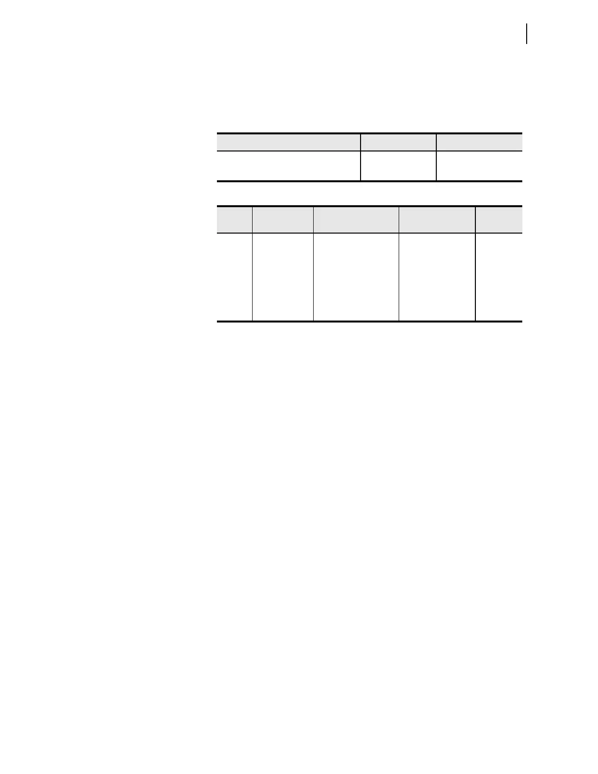
Latch bits are nonvolatile storage locations for Boolean information. Latch
bits are in several settings areas of the relay, as shown in Table 14.11. Latch
bits have two input parameters, Reset and Set, and one Latched Value, as
shown in Table 14.12.
Latch bits provide nonvolatile storage of binary information. A latch can have
the value of logical 0 or logical 1. Latch bits also retain their state through
changes in the active protection settings group. Because storage of latch bits is
in nonvolatile memory, the state of latch bits remains unchanged indefinitely,
even when power is lost to the relay.
As with logic latches used in digital electronics, each latch bit has a Set input
and a Reset input. The relay evaluates the latch bit value at the end of each
logic processing interval using the values for Set and Reset calculated during
the processing interval. Latch bits are reset dominant. If the Set and Reset
inputs are both asserted, the relay will reset the latch.
Latch bits are available in two different programming areas of the relay. First,
there are 32 latch bits, PLT01–PLT32, that are associated with protection
settings. Second, there are 32 latch bits, ALT01–ALT32, available in
automation free-form programming. You can view the status of individual
latch bits in the Relay Word using the TARGET command. Use the TAR
PLTnn command or the TAR ALTnn command to view the Relay Word row
containing the protection or automation latch bit specified by the two-digit
number nn. You can also view the status of latch bits through the relay LCD
front-panel display by selecting
RELAY ELEMENTS from the Main Menu and
scrolling through the rows of Relay Word bits.
Protection Latch Bits
Program the 32 latch bits, PLT01–PLT32, in the protection free-form
SEL
OGIC control equation programming area. There is a separate protection
free-form SEL
OGIC control equation programming area associated with each
protection settings group. The latches in protection can have separate
programming for Set and Reset in each protection settings group. While each
protection latch value remains unchanged for a change in the active protection
settings group, you can enter different Set and Reset programming for each
protection settings group.
Table 14.11 Latch Bit Quantities
Type Quantity Name Range
Protection free-form latch bits 32 PLT01–PLT32
Automation latch bits 32 ALT01–ALT32
Table 14.12 Latch Bit Parameters
Type Item Description Setting
Name
Examples
Input Reset Reset latch when on Boolean SELOGIC
control equation
PLT01R
ALT01R
Input Set Set latch when on Boolean SEL
OGIC
control equation
PLT01S
ALT01S
Output Latched Value Latched Value of 0 or 1 Value for use in
Boolean SEL
OGIC
control equations
PLT01
ALT24