P.3.132
SEL-411L Relay Protection Manual Date Code 20151029
Protection Functions
Fault Location
When in outstation mode, the relay always displays the locally-calculated
fault information and sends the fault location information to the master relay.
After it collects the fault location information from all outstation relays, the
master relay displays the information from the remote relay with the faulted
line segment.
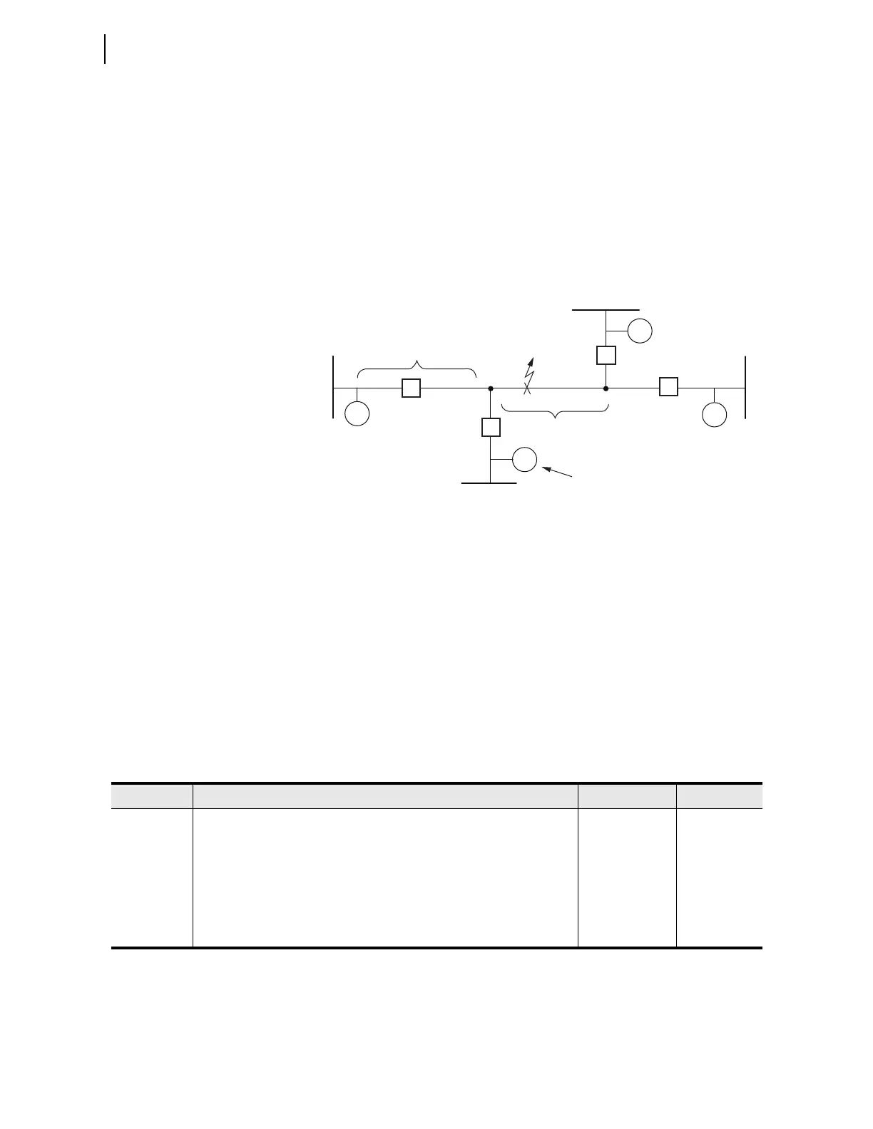
The relay can calculate fault locations on lines with as many as two tap points.
Figure 3.79 shows a line with two tap points (TAP 1 and TAP 2), and
Table 3.63 describes the settings necessary to configure the fault locator.
Figure 3.79 correlates the settings in Table 3.63 with the appropriate line
segments (only magnitudes shown for brevity). In this example, Relay RL
(local relay) is being set. For the discussion below, assume Fault F1 is ten
percent from TAP 1.
Fig ure 3.79 Line With Two TAP Po ints
It is not necessary to enter the length of the last pieces of the line (between
TAP 2 and R2 or TAP 2 and R4). Because the relays communicate with each
other, this information is redundant. When a fault occurs, each relay calculates
the distance to the fault with reference to the first tap point for that particular
relay. For example, for Fault F1, Relay RL determines if the fault is on the
portion of the line between RL and TAP 1, and Relay R3 determines if the
fault is on the portion of the line between R3 and TAP 1. Relays R2 and R4 do
similar calculations with respect to TAP 2.
In this example, all four relays determine that the fault is beyond the first tap
point. Each relay now calculates the fault position on the portion of the line
between the two tap points with reference to the first tap point for that
particular relay. Therefore, Relay RL and R3 report the fault position as
10 percent of the line length between TAP 1 and TAP 2, and Relays R2 and R4
report the fault position as 90 percent of the length between TAP 1 and TAP 2.
TAP 1
TAP 2
RL
R3
R2
R4
Z1RTMAG
Z0RTMAG
LLR
Z1TTMAG
Z0TTMAG
LLT
STRTID
F1
Table 3.62 Fault Location Settings for 2-, 3-, and 4-Terminal Lines With One TAP Point
Name Description Range Default (5A)
Z1RTMAG
a
a
This setting is hidden if E87CH = 2SS, 2SD or 2E. In this case, Z1RTMAG := Z1MAG.
Positive-sequence line impedance magnitude from the relay to the tap point 0.00–255
secondary
7.80
Z1RTANG
b
b
This setting is hidden if E87CH = 2SS, 2SD or 2E. In this case, Z1RTANG := Z1ANG.
Positive-sequence line impedance angle from the relay to the tap point 5.00°–90° 84.00
Z0RTMAG
c
c
This setting is hidden if E87CH = 2SS, 2SD or 2E. In this case, Z0RTMAG := Z0MAG.
Zero-sequence line impedance magnitude from the relay to the tap point 0.00–255
secondary
24.80
Z0RTANG
d
d
This setting is hidden if E87CH = 2SS, 2SD or 2E. In this case, Z0RTANG := Z0ANG.
Zero-sequence line impedance angle from the relay to the tap point 5.00°–90° 81.50
LLR Length of the line segment from the relay to the tap point 0.10–999 100.00