P.12.34
SEL-411L Relay Protection Manual Date Code 20151029
Bay Control
ACSELERATOR QuickSet SEL-5030 Software Bay Control Screens
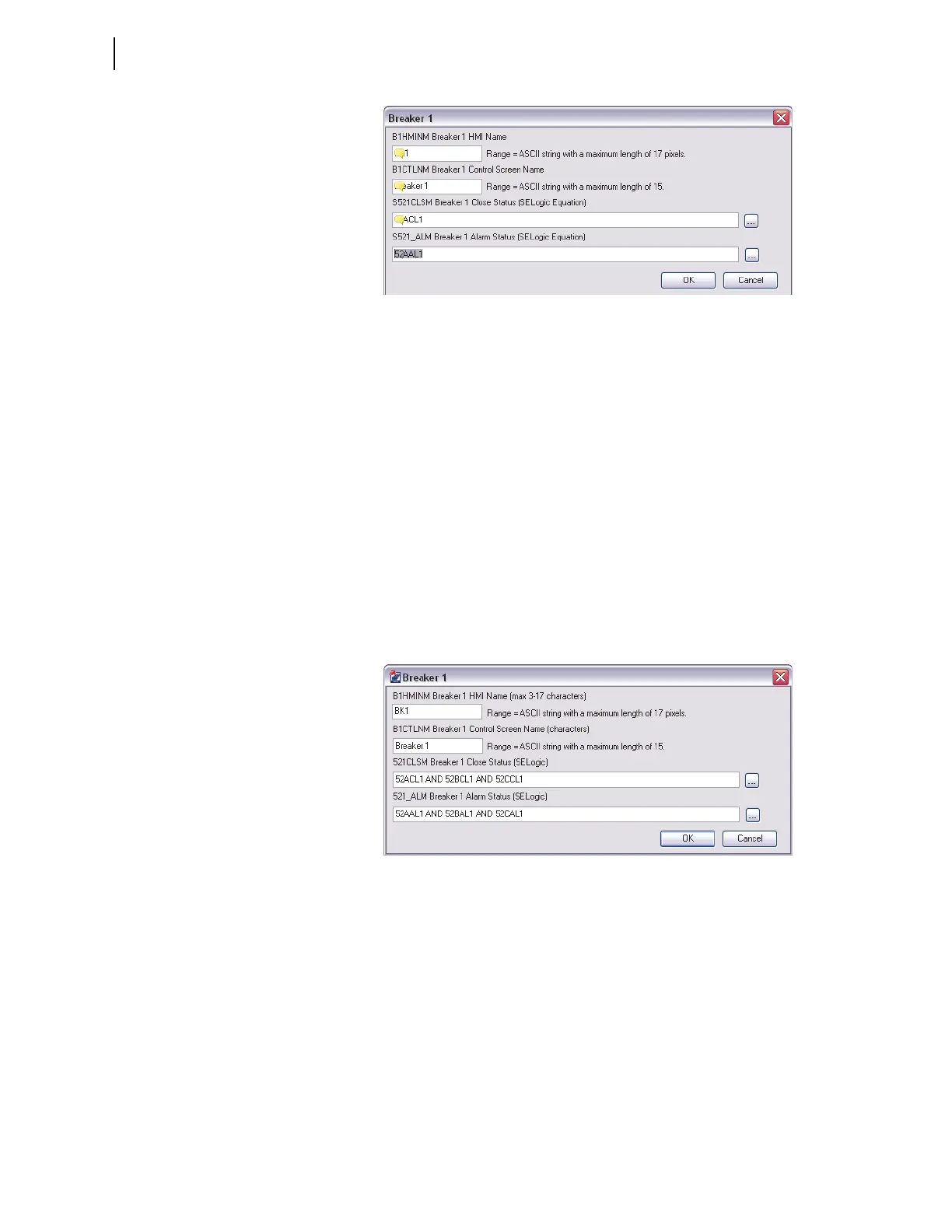
Figure 12.22 Breaker 1 Settings
Breaker 1 HMI Name Label. HMI name is limited to a maximum of 17
pixels and serves to identify the equipment, i.e., breaker and disconnects.
Enter a more descriptive name at the next setting, Breaker 1 Control Screen
Name.
BWHMINM := BK1
Breaker 1 Control Screen Name Label. Enter a descriptive breaker
name (up to 15 characters) for the circuit breaker in the control screens.
B1CTLNm := Breaker 1
Breaker 1 Close Status. This SELOGIC control equation reports breaker
close status and breaker alarm status. Any Relay Word bit can be programmed
into this SEL
OGIC control equation, as well as logical operators. The equations
below return the breaker status and any breaker alarm conditions.
521CLSM := 52ACL1
521_ALM := 52AAL1
Figure 12.23 Break 1 Settings for a Single Pole Breaker
In case of a single-pole breaker, set the breaker close status to be the AND
combination of each single-pole close status. For the breaker alarm status bit,
use the OR combination of each single-pole alarm status.
521CLSM := 52ACL1 AND 52BCL1 AND 52CCL1
521_ALM := 52AAL1 OR 52BAL1 OR 52CAL1
Analog Display
The one-line diagrams in the relay contain as many as six analog quantity
display points. The MIMIC settings selected in this example displays six
analog display points. If no analog display points are required, leave the
setting(s) blank, for the relay displays only the defined display points.