P.14.22
SEL-411L Relay Protection Manual Date Code 20151029
SELOGIC Control Equation Programming
SEL
OGIC Control Equation Elements
In this example, timer AST01 times the quantity IN201 AND IN202 and
turns on when the total time reaches 7.5 seconds. If the Input,
AST01IN, is on for approximately 1 second every minute, the Output,
AST01Q, will turn on during the eighth minute, when the accumulated
elapsed time exceeds 7.5 seconds.
In free-form programming, the relay evaluates the timer at the timer Input
SEL
OGIC control equation (PSTnnIN or ASTnnIN). If you enter an expression
for the timer Reset (PSTnnR or ASTnnR) or Preset Time (PSTnnPT or
ASTnnPT), the values for Reset and Preset Time that the relay uses are the last
values that the relay calculates before the input SEL
OGIC control equation
calculation. Because the relay uses the last values for Reset and Preset Time
value in this manner, we recommend for most applications that you enter the
Preset Time, Reset, and Input statements together in the order shown in
Example 14.8. You can view the current state of the timer by assigning the
elapsed time output of the sequencing timer to a math variable. Example 14.8
shows how you would assign the elapsed time output for automation sequence
timer AST01 to automation math variable AMV256. To see the elapsed time
value, issue the MET AMV command to display the values of the automation
math variables. Likewise, you can assign the elapsed time output of a
protection sequence timer to a protection math variable.
The elapsed time output is stored in volatile memory. Elapsed time resets to
zero for both protection and automation sequential timers when relay power
cycles, you change settings or settings groups, or you perform any function
that reboots the relay.
Counters
Use counters to count changes or edges in Boolean values. Each time the value
changes from logical 0 to logical 1 (a rising edge), the counter Current Value
increments. Counters are available in the protection free-form area and automation
free-form area, as shown in Table 14.17. Counters have three input parameters,
Input, Preset Value, and Reset; and two outputs, Current Value and Output as listed
in Table 14.18.
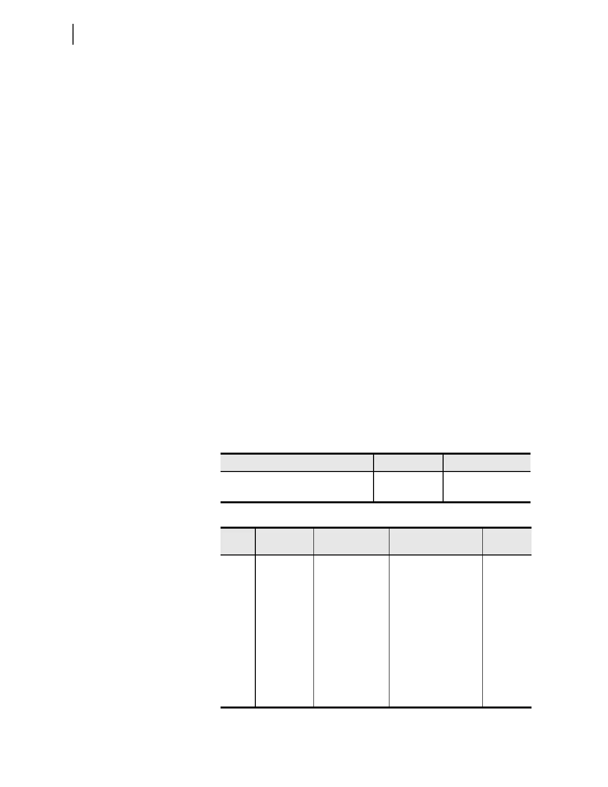
Table 14.17 Counter Quantities
Type Quantity Name Range
Protection counters 32 PCN01–PCN32
Automation counters 32 ACN01–ACN32
Table 14.18 Counter Parameters
Type Item Description Setting
Name
Examples
Input Input Value that the relay
counts
Boolean SELOGIC con-
trol equation setting
PCN01IN
ACN09IN
Input Preset Value Number of counts
before the output
turns on
Constant or expression
for the number of counts
PCN01PV
ACN09PV
Input Reset Counter reset Boolean SEL
OGIC con-
trol equation setting
PCN01R
ACN09R
Output Current Value Current accumu-
lated count
Value for math SEL
OGIC
control equations
PCN01CV
ACN09CV
Output Output Counter output Value for Boolean
SEL
OGIC control equa-
tions
PCN01Q
ACN09Q