P.2.25
Date Code 20151029 Protection Manual SEL-411L Relay
Installation
Connection
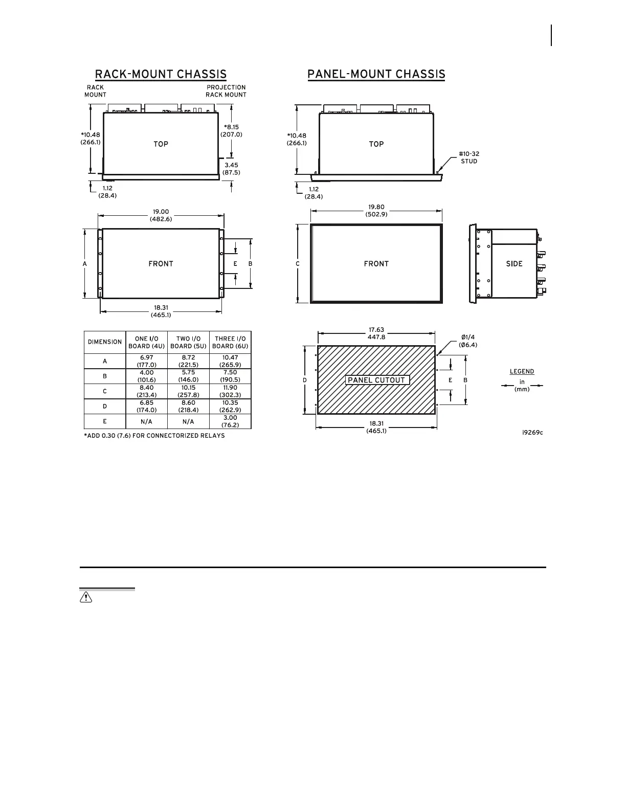
Figure 2.21 Chassis Dimensions
Panel Mounting
Place the panel-mount versions of the relay in a switchboard panel. See the
drawings in Figure 2.21 for panel cut and drill dimensions (these dimensions
apply to both the horizontal and vertical panel-mount relay versions). Use the
supplied mounting hardware to attach the relay.
Connection
The relay is available in many different configurations, depending on the
number and type of control inputs, control outputs, and analog input
termination you specified at ordering. This subsection presents a
representative sample of relay rear-panel configurations and the connections
to these rear panels. Only horizontal chassis are shown; rear panels of vertical
chassis are identical to horizontal chassis rear panels for each of the 4U, 5U,
and 6U sizes.
When connecting the relay, refer to your company plan for wire routing and
wire management. Be sure to use wire that is appropriate for your installation
with an insulation rating of at least 90°C.
Insufficiently rated insulation can
deteriorate under abnormal operating
conditions and cause equipment
damage. For external circuits, use
wiring of sufficiently rated insulation
that will not break down under
abnormal operating conditions.