P.12.3
Date Code 20151029 Protection Manual SEL-411L Relay
Bay Control
Disconnect Logic
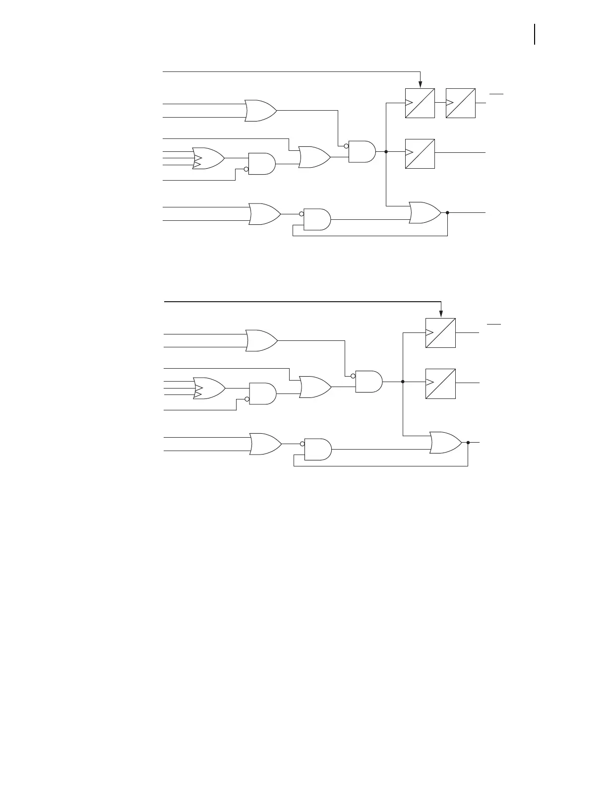
Figure 12.1 Disconnect Switch Close Logic
Figure 12.2 Disconnect Switch Open Logic
Disconnect Switch Close and Open Control Logic Status Inputs
89CLSm, 89OPEm
Disconnect switch close logic (Figure 12.1) and open logic (Figure 12.2)
generate Relay Word bits 89CLSm and 89OPEm which drive the open and
close operations. To ensure that an open and close disconnect signal cannot
occur at the same time, 89CLSm and 89OPEm also block operation of the
opposing logic. Therefore, Relay Word bit 89CLSm is an input to the
disconnect open logic, and Relay Word bit 89OPEm is an input to the
disconnect close logic.
89CBLm, 89OBLm
The 89CBLm and 89OBLm SELOGIC control equations provide an alternative
customizable method for blocking the initiation of a disconnect switch open or
close command, respectively.
Close Immobility Timer
89CITm
0
CYC
*89CIRm
(default setting:
NOT 89OPNm)
89ALm
*89CRSm
(default setting:
89CLm OR 89CSIm)
Relay
Word
Bits
* SEL
OGIC
control equation
** This SEL
OGIC
control equation
processed at 1/8 cycle
89CIMm
89CLSm
(Reset)
0 cyc
60
CYC
5
2
3
Close Seal-in Timer
89CSTm
0
CYC
*89CBLm
89OPEm
89CCMm
89CCm (ASCII)
**89CCNm (k – 1/8 cyc.)
**89CCNm (k)
*LOCAL
89CSIm
3
4
2
1
1
Open Immobility Timer
89OITm
60
CYC
*89OIRm
(default setting:
NOT 89CLm)
89ALm
*89ORSTm
(default setting:
89OPNm OR 89OSIDm)
Relay
Word
Bits
* SELOGIC control equation
** This SELOGIC control equation
processed at 1/8 cycle
89OIMm
89OPEm
(Reset)
5
2
3
Open Seal-in Timer
89OSTm
0
CYC
*89OBLm
89CLSm
89OCMm
89OCm (ASCII)
**89OCNm (k – 1/8 cyc.)
**89OCNm (k)
*LOCAL
89OSIm
3
4
2
1
1