P.4.18
SEL-411L Relay Protection Manual Date Code 20151029
Autoreclosing and Synchronism-Check
Two-Circuit-Breaker Autoreclosing
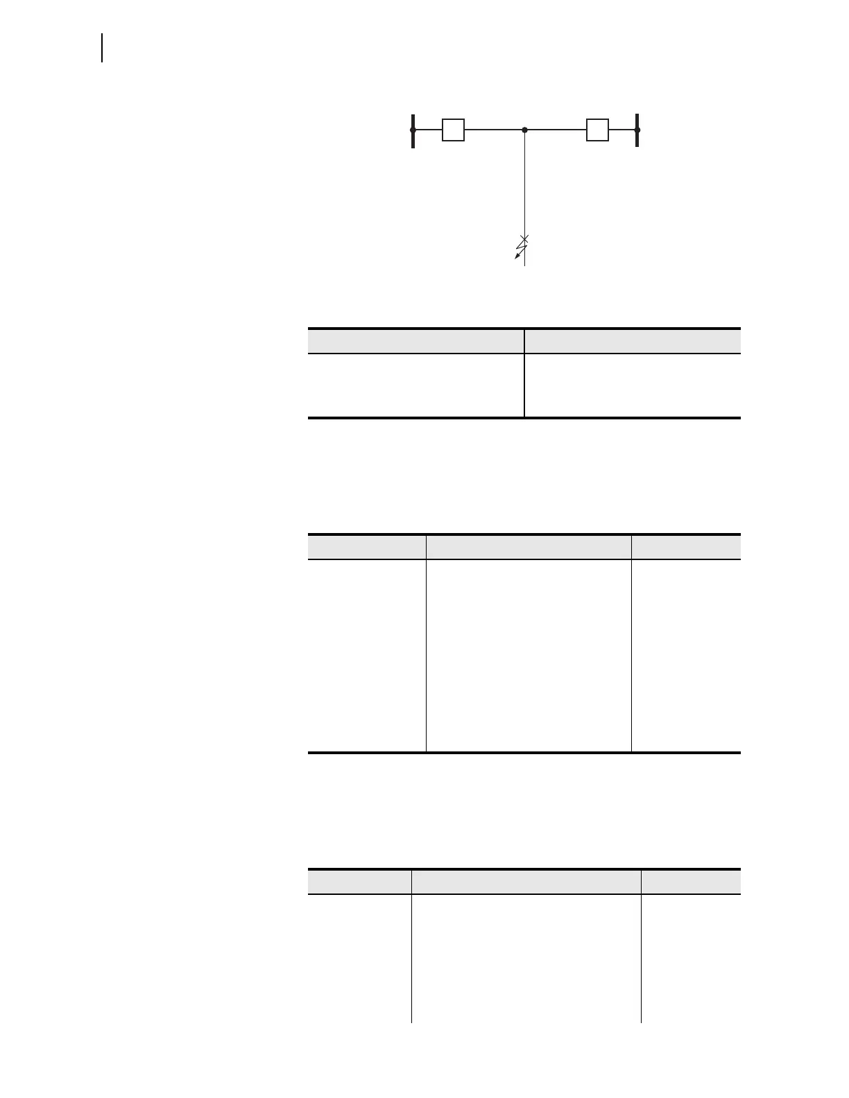
Figure 4.3 Multiple Circuit Breaker Arrangement
Reset State and 79CY3 Cycle State
Prior to receiving initiation for a three-phase fault, the autoreclose logic resets
for both circuit breakers. Table 4.7 defines the logical state of the autoreclose
logic for this example prior to the initiation of an autoreclose cycle.
Lockout State
Circuit Breaker BK1 fails to close when the first three-pole open interval
expires and goes to lockout. Circuit Breaker BK2 goes to lockout. Table 4.8
defines the logical state of the autoreclose logic at this point.
Table 4.6 Leader/Follower Selection
Setting Label Value
SLBK1 1
SLBK2 0
FBKCEN 0
Bus 1
(Leader) (Follower)
Line
Three-phase fault
Bus 2
BK2
BK1
Table 4.7 Example One: Reset and 79CY3 States
Relay Word Bit Description Logical State
NBK0 No Active Breakers in Reclose Scheme 0
NBK1 One Breaker Active in Reclose Scheme 0
NBK2 Two Active Breakers in Reclose Scheme 1
LEADBK0 No Leader Breaker 0
LEADBK1 Leader Breaker = Breaker 1 1
LEADBK2 Leader Breaker = Breaker 2 0
FOLBK0 No Follower Breaker 0
FOLBK1 Follower Breaker = Breaker 1 0
FOLBK2 Follower Breaker = Breaker 2 1
Table 4.8 Example One: Lockout State (Sheet 1 of 2)
Relay Word Bit Description Logical State
NBK0 No Active Breakers in Reclose Scheme 1
NBK1 One Breaker Active in Reclose Scheme 0
NBK2 Two Active Breakers in Reclose Scheme 0
LEADBK0 No Leader Breaker 1
LEADBK1 Leader Breaker = Breaker 1 0
LEADBK2 Leader Breaker = Breaker 2 0