P.14.21
Date Code 20151029 Protection Manual SEL-411L Relay
SELOGIC Control Equation Programming
SEL
OGIC Control Equation Elements
exceeds the Preset Time. Whenever the Reset is on, the relay sets the Output
to zero, then clears the Elapsed Time, and stops accumulating time (even if
Input is on).
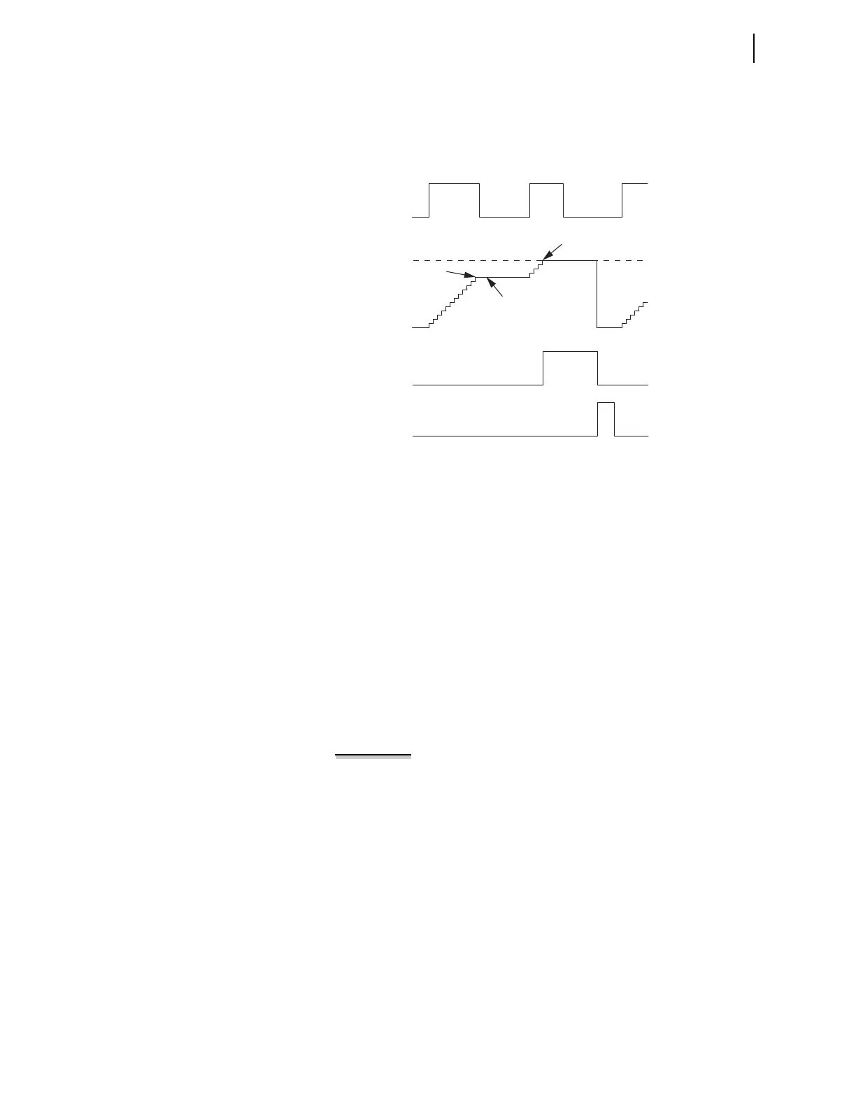
Figure 14.8 is a timing diagram for typical sequencing timer operation.
Figure 14.8 Sequencing Timer Timing Diagram
Timers in protection programming operate in cycles, while timers in
automation programming operate in seconds. As with sequencing timers,
operation depends on the logic processing interval. For protection
programming, the logic processing interval is 1/8 cycle, so the relay
effectively rounds up all operation to the nearest 1/8 cycle. With automation
programming, the execution interval depends on the amount of automation
programming. Determine the average automation execution interval with the
STATUS S command.
The automation timers operate using a real time clock. Each time the relay
evaluates the Input (ASTnnIN) the relay adds the elapsed time since the last
execution to the Elapsed Time (ASTnnET). The accuracy of the timer in
stopping and starting when the input of the timer turns on averages half an
automation execution cycle. If you change automation free-form programming,
you must also check the new automation average execution cycle to verify that you
will obtain satisfactory accuracy for your application. Example 14.8 describes
typical timer programming and describes the resulting operation.
EXAMPLE 14.8 Automation Sequencing Timer Programming
The equations below are an example of programming for an
automation sequencing timer, AST01. Each timer input is
programmed as a separate statement in automation SEL
OGIC control
equation programming.
# Example programming of sequencing timer to time Input IN201 and IN202
AST01PT := 7. 5 # Timer Preset Time of 7.5 seconds
AST01R := RB03 # Reset timer when RB03 turns on
AST01IN := IN201 AND IN202 # Timing time when IN201 and IN202 are on
ASV001 := AST01Q # ASV001 tracks output of timer
AMV256 := AST01ET # AMV256 tracks timing progress
Elapsed Time
Increases While
Input Is On
Elapsed Time
Does Not Reset
When Input Is Off
Elapsed Time Reaches
Preset Value
Elapsed Time
PST01ET
Input
PST01IN
Reset
PST01R
Output
PST01Q
Preset Value
PST01PT