P.4.50
SEL-411L Relay Protection Manual Date Code 20151029
Autoreclosing and Synchronism-Check
Synchronism Check
Single-Phase Voltage
Inputs
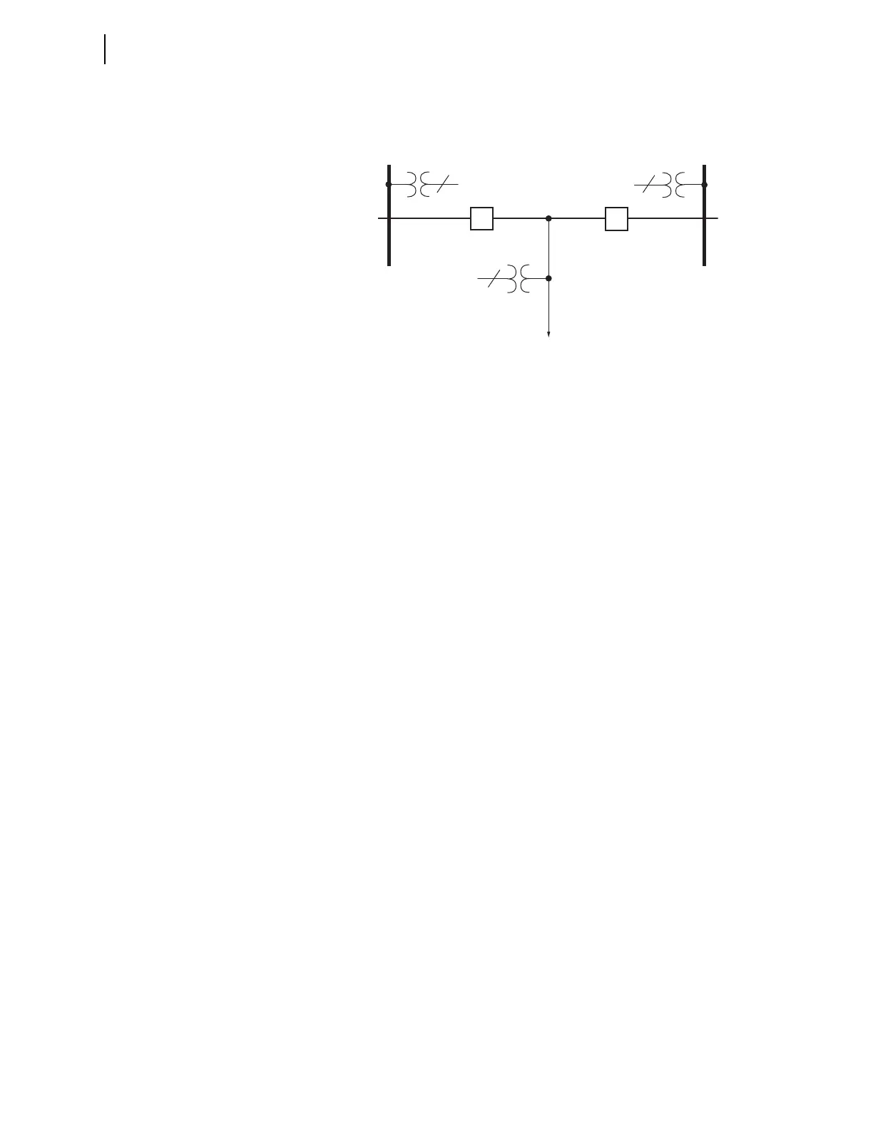
Figure 4.20 shows single-phase voltage transformers (1 PT) on Bus 1 and
Bus 2. Use these single-phase voltage sources to perform a synchronism-
check across the two circuit breakers.
Figure 4.20 Synchronism-Check Voltages for Two Circuit Breakers
Synchronism check occurs on a single-phase voltage basis—see the single-
phase potential transformers (1 PT) shown on each bus in Figure 4.20. The
assumption is that, if the monitored single-phase voltage inputs are in phase
(within a settable voltage angle difference) and are healthy (within a settable
voltage magnitude window), the other phase-to-neutral voltages are likewise
in phase and healthy. The line voltage source is three-phase, but you only need
a single-phase bus voltage to perform a synchronism-check across the
corresponding circuit breaker. The relay uses the three-phase voltage from the
line for other functions such as distance protection and metering.
Synchronism-Check
Settings
This example uses a two-circuit breaker arrangement (see Figure 4.20). Set
the synchronism-check enable settings:
E25BK1 := Y Synchronism-Check for Circuit Breaker BK1 (Y, N)
E25BK2 := Y Synchronism-Check for Circuit Breaker BK2 (Y, N)
If you are using the relay on a single circuit breaker, enable synchronism-
check for only one circuit breaker (E25BK1 := Y and E25BK2 := N).
Figure 4.21 shows the correspondence between the synchronism-check
settings and the two-circuit breaker application example. All of these settings
are listed in Section 5: Settings. The following subsections explain these
settings and include an explanation of Alternative Synchronism-Check
Voltage Source 2 settings (see Figure 4.31).
Bus 2
Bus 1
Line
BK2
BK1
1
3
1
. . . . . .
. . .