P.7.37
Date Code 20151029 Protection Manual SEL-411L Relay
Front-Panel Operations
Operation and Target LEDs
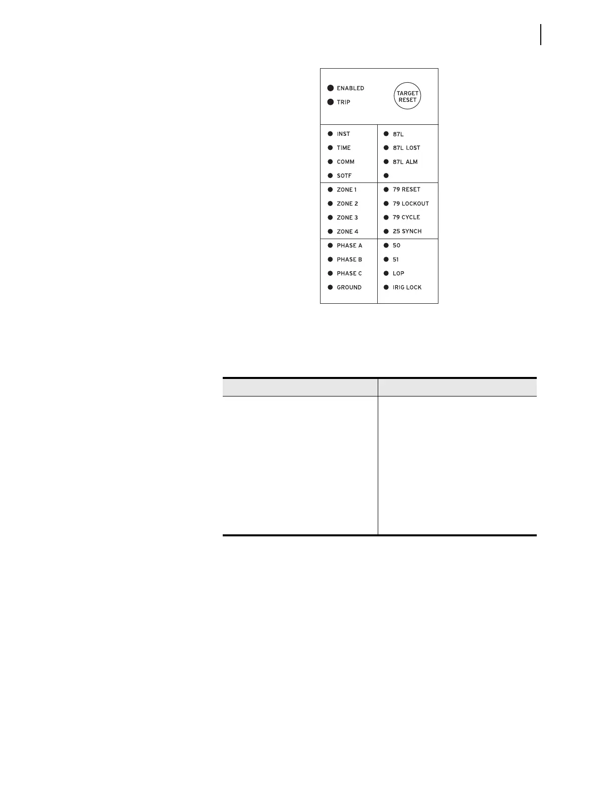
Figure 7.45 Factory Default Front-Panel Target Areas
Figure 7.45 shows the arrangement of the operation and target LEDs region
into several areas described in Table 7.11.
Operational
The ENABLED LED indicates that the relay is active. Trip events illuminate the
TRIP LED. The prominent location of the TRIP LED in the top target area helps
you recognize a trip event quickly. Program settings EN_LEDc and TR_LEDc
to determine the color of the respective LED. Options include red or green.
TARGET RESET and Lamp Test
For a trip event, the relay latches the trip-involved target LEDs (except for the
ENABLED LED and the Recloser Status area LEDs). Press the TARGET RESET
pushbutton to reset the latched target LEDs. When a new trip event occurs and
you have not reset the previously latched trip targets, the relay clears the
latched targets and displays the new trip targets.
Pressing the TARGET RESET pushbutton illuminates all the LEDs. Upon
releasing the TARGET RESET pushbutton, two possible trip situations can exist:
the conditions that caused the relay to trip have cleared or the trip conditions
Tab l e 7.1 1 Fr o n t - Pa n e l Ta rg et L E D s
Label Function
ENABLED, TRIP
Operational
INST, TIME, COMM, SOTF
Trip Type
ZONE 1, ZONE 2, ZONE 3, ZONE 4
Zone Activated
PHASE A, PHASE B, PHASE C, GROUND
Phase(s) or Ground
87L, 87L LOST, 87L ALM
Current Differential Protection Information
79 RESET, 79 LOCKOUT,
79 CYCLE, 25 SYNCH
Recloser and Synchronizing Status
50, 51, LOP, IRIG LOCKED
Instantaneous and Time-Delayed Overcur-
rent. LOP and IRIG
(1)
(2)
(3)
(4)
(5)
(6)
(7)
(8)
(9)
(10)
(11)
(12)
(13)
(14)
(15)
(16)
(17)
(18)
(19)
(20)
(21)
(22)
(23)
(24)