P.3.191
Date Code 20151029 Protection Manual SEL-411L Relay
Protection Functions
Quadrilateral Phase Distance Elements
Quadrilateral Phase Distance Elements
The -1 relay has two groups of quadrilateral phase distance elements, viz,
high-speed elements, and conventional elements. There are five zones
(Zones 1–5) of conventional elements, and three zones of high-speed elements
(Zones 1–3). Reach settings for Zones 1–3 elements are the same for the two
groups. For example, setting XP1 = 4 sets the Zone 1 reactance reach for
both high-speed elements and conventional elements to 4 Ohms secondary.
Notice that setting XPx (x = 1 – 5 or x = 1 – 3) is an impedance (not reactance)
setting. You can set the impedance and resistive (RPx) reach for each zone
independently.
The relay also has five independent zones of mho phase distance protection
(see mho phase distance elements for more information). Although the mho
and quadrilateral phase elements are independent, you can enable both at the
same time. To this end, the outputs from the mho and quadrilateral phase
elements are ORed to a single protection output (see Figure 3.126,
Figure 3.128, and Figure 3.129).
NOTE: It is recommended to enable
the phase mho elements in
conjunction with the phase
quadrilateral elements to provide
detection for phase-to-phase faults
during single pole open (SPO)
conditions.
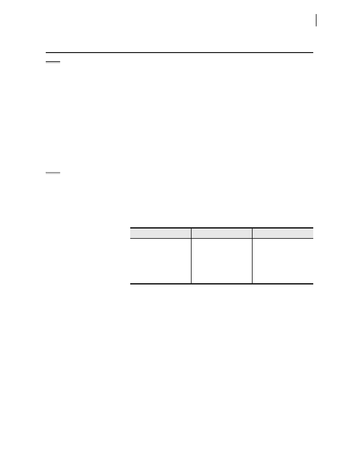
For both the high-speed and conventional quadrilateral phase distance
elements, Zone 1 and Zone 2 distance elements operate in the forward
direction only. You can set Zone 3 for the high-speed elements and Zones 3–5
for the conventional elements to operate in either forward or reverse
directions. Table 3.97 summarizes the zone directional settings for the high-
speed and conventional elements.
The impedance reach for each zone of quadrilateral phase distance protection
lies on the line positive-sequence impedance angle (Z1ANG) rather than on
the ordinate (reactance) of the impedance plane. When setting the reactance
reach of the relay, do not convert the line impedance to a reactance. Enter the
impedance value at the line angle in the same way you would enter the
impedance value when setting a mho element. For example, if the line
impedance is Z = 2 +j15 (15.13 82.4° ) secondary, enter the following
settings for an 85 percent Zone 1 reach:
Z1ANG = 82.4°
XP1 = 12.86
(15.13 • 0.85)
Figure 3.130 shows the first three zones of the quadrilateral phase
characteristic. Notice that the right blinders are parallel to the line impedance,
and not parallel to the reactance axis. There is no setting for –RP, the left
blinder; this value is fixed at the negative value of the lowest forward looking
resistive RPn setting (n = 1–5). For example, if RP1 is set to RP1 = 3.8 , and
if RP1 is the minimum of RP1–RP5, then the left blinder setting becomes
–3.8 . Zones set to OFF (XPn = OFF), reverse looking zones (DIRn = R)
and zones not included in the E21XP setting are excluded from the
calculations to determine the minimum RP value in the forward direction.
NOTE: The -0 relay provides fast and
secure tripping, but does not have
high-speed distance elements. Typical
detection time for the -0 relay is
1.5 cycles.
Table 3.97 High-Speed and Conventional Element Directional Setting Summary
Zones High-Speed Elements Conventional Elements
Zone 1 Forward only Forward only
Zone 2 Forward only Forward only
Zone 3 Forward/reverse Forward/reverse
Zone 4 NA Forward/reverse
Zone 5 NA Forward/reverse