P.12.14
SEL-411L Relay Protection Manual Date Code 20151029
Bay Control
Bay Control Front-Panel Operations
one-line diagram. Once you enter the one-line diagram, navigation between
the disconnect switch and circuit breaker symbols in the one-line diagram is as
follows:
➤ Pressing the Right Arrow key highlights the elements from left-
to-right and top-to-bottom.
➤ When reaching the right-most bottom element, the following
Right Arrow keystroke “rolls over” and again highlights the left-
most top element.
➤ The Left Arrow key operates in reverse, i.e., from right-to-left,
and bottom-to-top.
➤ Select the highlighted symbol and display the corresponding
control screen if the LOCAL Relay Word Bit is asserted. ENT
➤ Go back to the previous screen: ESC
Circuit Breaker and
Disconnect
Definitions and State
Representations
Table 12.1 shows the apparatus definitions and symbols displayed on the one-
line diagram.
Each apparatus (circuit breaker or disconnect switch) can be in one of the
following six states:
➤ Open, not highlighted
➤ Open, highlighted
➤ Closed, not highlighted
➤ Closed, highlighted
➤ Intermediate, not highlighted (intermediate = transition
between open and closed states)
➤ Intermediate, highlighted
Table 12.2 describes how the one-line diagram represents the different states
of the breakers, and how highlighting the breaker affects the display of the
symbol.
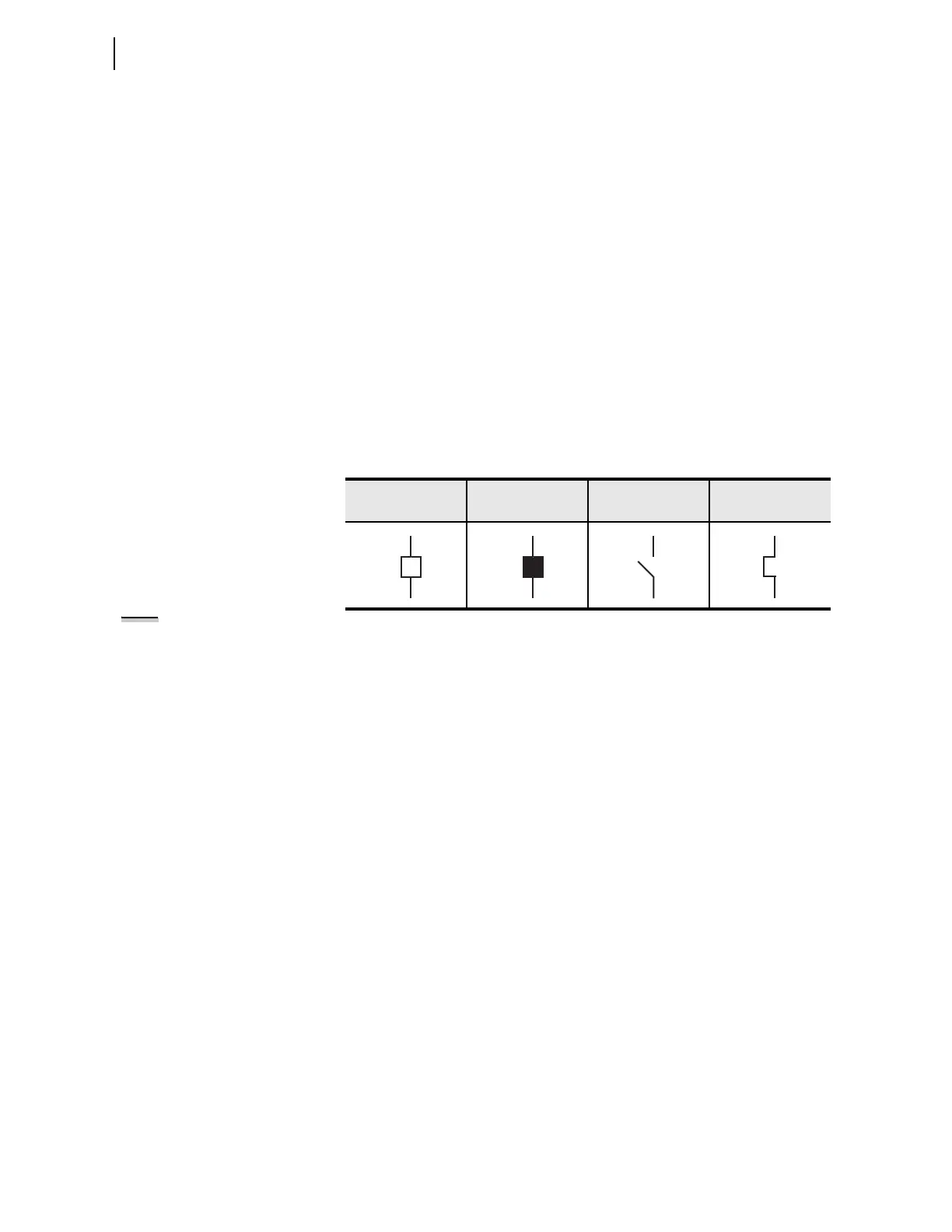
Table 12.1 Circuit Breaker and Disconnect Switch Definitions
Circuit Breaker
Open
Circuit Breaker
Closed
Disconnect Open Disconnect Closed
NOTE: The intermediate states only
apply to disconnect switches because
circuit breaker operations have a
short duration.