P.12.19
Date Code 20151029 Protection Manual SEL-411L Relay
Bay Control
Bay Control Front-Panel Operations
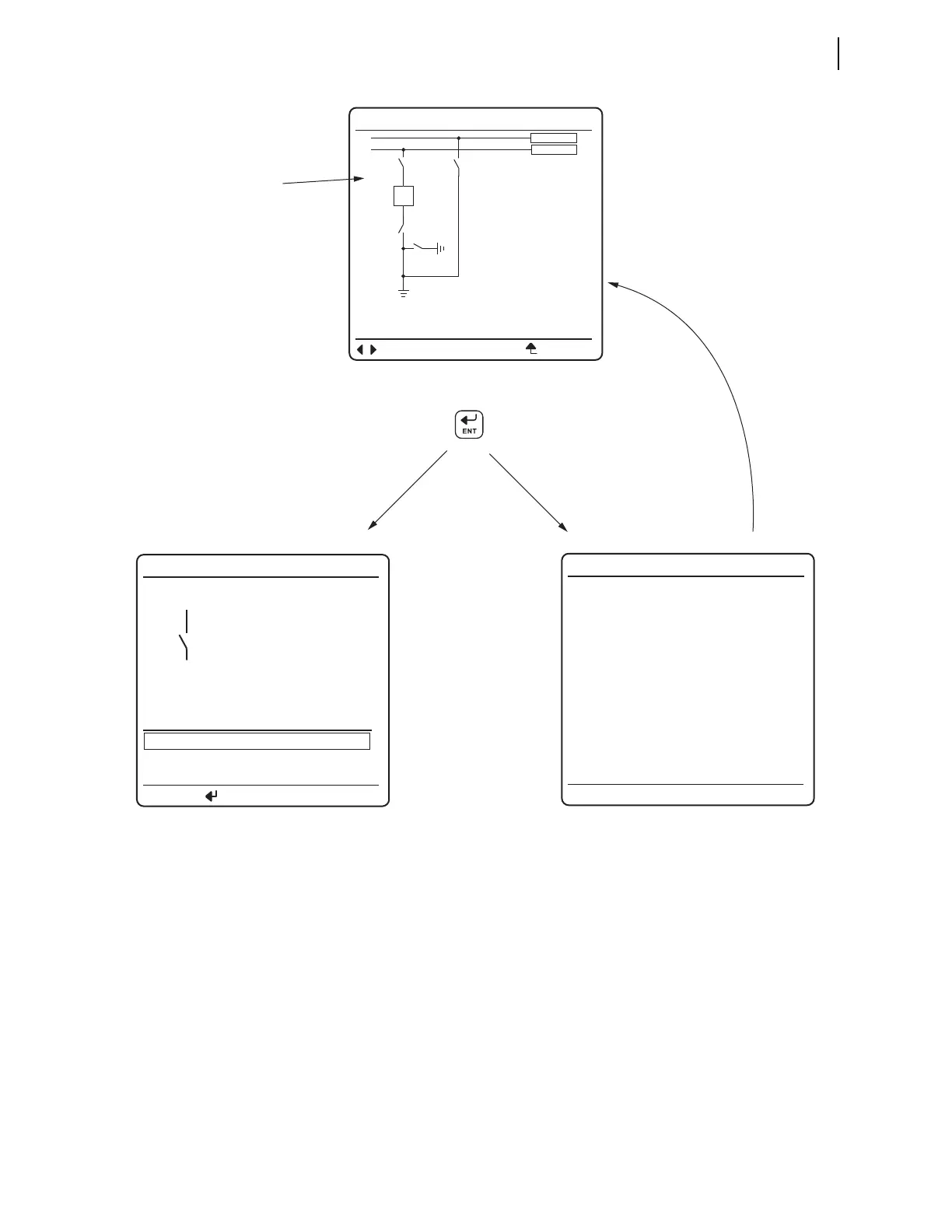
Figure 12.10 Screens for Disconnect Switch Selection
Figure 12.11–Figure 12.13 show all the possible screens during an open-to-
close operation of Disconnect 1. Operation of Disconnect 2–10 is identical.
Close-to-open operations are similar, the only difference being that the open
Relay Word bits apply instead of the close Relay Word bits. The screen in
Figure 12.11 (a) is displayed after you press the ENT pushbutton with
Disconnect 1 open and highlighted in the one-line diagram. Figure 12.11 (a) is
Screen (b) in Figure 12.10.
When you enter the disconnect screen in Figure 12.11 (a), the state that the
disconnect switch is in is highlighted, in other words, if Relay Word bit
89OPN01 is asserted, the
OPEN DISCONNECT text has a box drawn around it.
To close the disconnect switch, use the Up Arrow or Down Arrow pushbutton to
highlight the
CLOSE DISCONNECT text.
<BAYNAME> <BAYNAME>
OPEN DISCONNECT
CLOSE DISCONNECT
STATUS
<DmCTLN>
PRESS TO ACTIVATE
BAY not in
LOCAL Control!
Cannot issue
controls.
Press Enter with disconnect
highlighted
Highlighted
(disconnect
highlighted)
(a) Bay Screen
(c) LOCAL bit NOT asserted
(b) Disconnect Control Screen
If LOCAL
bit asserted
If LOCAL bit
NOT asserted
After message timeout,
screen (a) is displayed
m = 1–5
<BAY 1>
BUSNAM1
<DmHMIN>
BUSNAM2
ESCNAVIG
I:99999 A
V:99999 kV
P:99999 MW
Q:99999 MV
<DmHMIN>
<DmHMIN>
<BmHMINM>
<DmHMIN>