P.3.74
SEL-411L Relay Protection Manual Date Code 20151029
Protection Functions
87L Differential Elements
applies a 3x3 matrix to properly reflect the self and mutual capacitances of the
line. The compensation therefore works for both balanced and unbalanced
conditions. The relay determines the capacitances according to the
zero-sequence and positive-sequence line susceptances you provide as settings
(87CCB0 and 87CCB1, respectively). By applying the proper tap adjustment
(87TAPCC), the relay scales the charging current adequately to the 1 pu base
of the 87L zone.
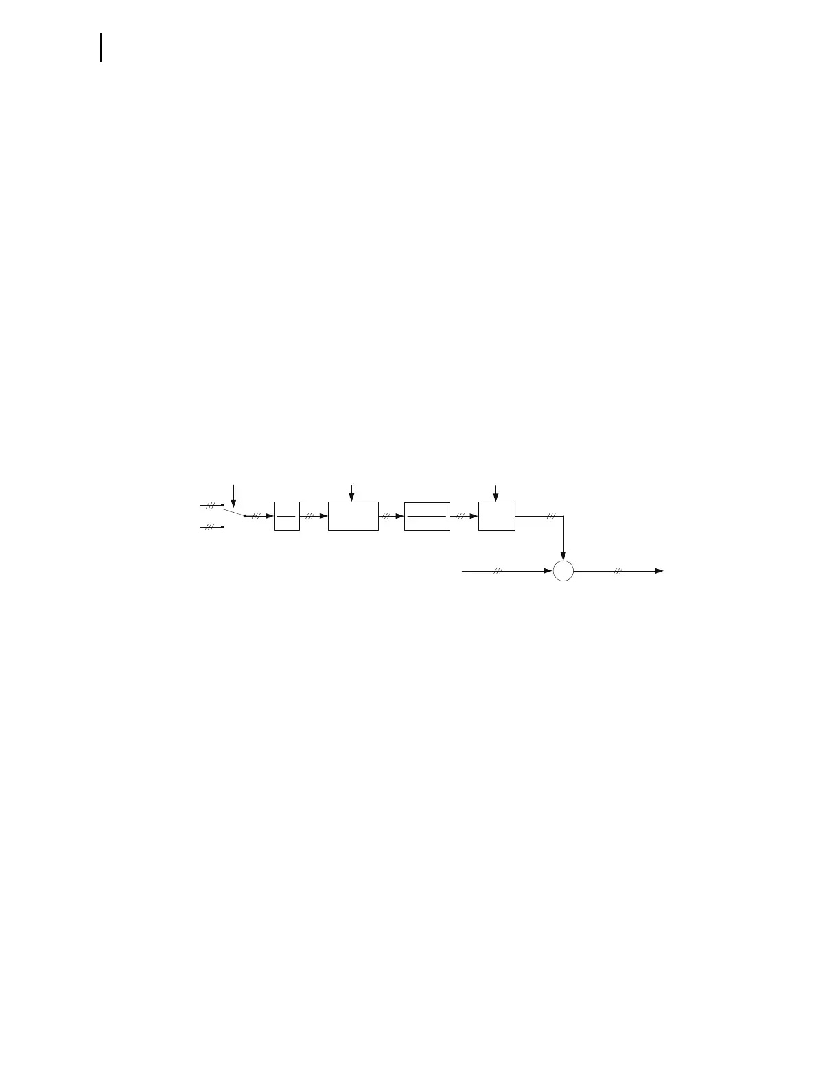
The local relay calculates this total line charging current based on the local
voltage and then multiplies this current value by the 87MCC value (see
Figure 3.40) to determine the specific portion of the line charging current to
compensate for at the local terminal. In this determination, the relay
recognizes the total number of terminals compensating for the line charging
current at the time. The local relay then subtracts the fraction of line charging
current from the measured local 87L currents. As a result, each terminal uses
already compensated currents. The sum of these fractional compensating
currents equals the total line charging current, to provide full compensation of
the differential signal for the line charging current. This compensation occurs
in the time domain (i.e., on samples) and automatically benefits not only the
phase 87L element (87LP), but also the sequence 87L elements (87LQ and
87LG), supervisory functions (external fault detection, disturbance detection,
open CT detection), and the multi-ended fault locator.
Figure 3.41 Line Charging Current Calculations and Removal
Refer to 87L Theory of Operation for an explanation of how removing the line
charging current from the differential current benefits the Generalized Alpha
Plane operating characteristic of the relay.
Note that the lump parameter line model provides the basis for the relay line
charging current compensation method. The relay effectively uses an average
voltage among all compensating line terminals in conjunction with the lump
capacitance of the entire line. This approach becomes less accurate at higher
frequencies, where the lump parameter model and an actual long line do not
match closely.
Note that charging current compensation is accurate in the passband of the
full-cycle cosine filters the 87L function uses. In the stopband of the full-cycle
cosine filters, inaccuracy of charging current compensation is irrelevant
because the filters block high frequency components. To ensure secure
operation for frequencies in the transition band of the full-cycle cosine filters,
the relay measures the amount of high frequency components in the
differential signal and boosts the restraint terms accordingly to counter the
finite accuracy of compensation (see Figure 3.42).
A combination of removing the line charging current in the cosine filter
passband from the differential signal and boosting the restraint terms with the
uncompensated high frequency components in the differential signal has a
doubly positive effect on the Generalized Alpha Plane, as 87L Theory of
Operation explains.
Σ
-
Φ = A, B, C
Setting
87LINEV
V
ΦYCal
V
ΦZCal
Setting
87CCB0
87CCB1
87MCC
multiplier
Charging current
contribution from
the local terminal
(samples)
Local Current
(measured, samples)
Local Current
(87L input, samples)
1
87TAPCC
[3x3] matrix
multiplication
d
dt
multiply