P.2.39
Date Code 20151029 Protection Manual SEL-411L Relay
Installation
Connection
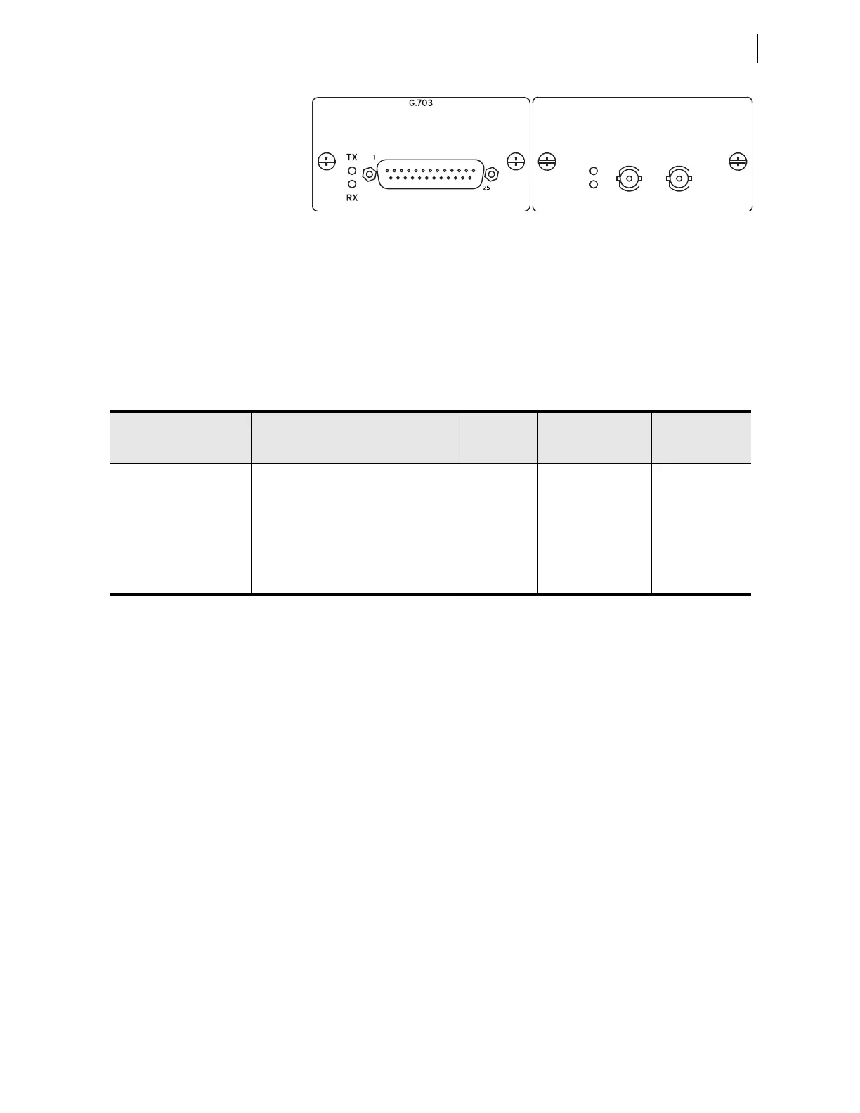
Figure 2.33 G.703 Card in the Bay 1 Position and a 850nm IEEE C39.94
Fiber Card in the Bay 2 Position
See Table 2.9 for the communications cards options.
Line Current Differential Communications Channel Interfaces
Bay 1 and/or Bay 2 are factory configured as one of the options listed in
Table 2.9. When the relay arrives, the channels are configured per your
ordering options.
Figure 2.34 and Figure 2.35 depict the signal names, pinout and direction at
the relay. All of the electrical 87L channel interface options on the relay are
isolated from the chassis to at least 1500 V rms. To maintain that isolation,
and to avoid ground loops, ground all cable shields only at the
communications equipment.
See Section 3: Protection Functions for channel interface configuration
settings, and for channel monitor settings.
850nm IEEE C37.94 FIBER
TX
RX
TX RX
Table 2.9 Current Differential Communication Interface Options
Data Interface Medium Data Rate Relay Connection
Maximum
Point-to-Point
Range
EIA-422 Electrical 64 k DB-25 male 100 ft
CCITT G.703 Electrical 64 k DB-25 male 100 ft
IEEE C37.94 Compliant 850 nm multimode fiber 64 k ST 2 km
IEEE C37.94 Modulation 1300 nm single-mode fiber 64 k ST 15 km
Direct Fiber 1300 nm multi- or single-mode fiber 64 k ST 30 km; 80 km
Direct Fiber 1550 nm single-mode fiber 64 k ST 120 km