P.3.26
SEL-411L Relay Protection Manual Date Code 20151029
Protection Functions
87L Theory of Operation
conditions, the current is not used and the detector provides permission for
87L to operate. This is to preserve dependability of the 87L operation. Once
the detector detects a disturbance, the 87DDR bit asserts for a minimum of 10
power cycles.
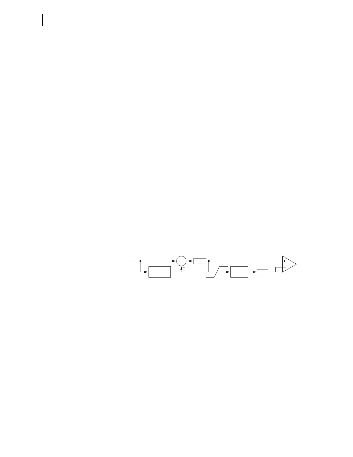
Both the local and remote parts of the disturbance detection logic use the same
adaptive algorithm depicted in Figure 3.17. The algorithm first calculates a
one-cycle difference for the input phasor IN. This operation executes on a
sample-by-sample basis and yields a very fast and sensitive response as a
result of the subtraction of the standing value in the input phasor IN.
Subsequently, the algorithm calculates the magnitude of this incremental
signal. The algorithm filters this magnitude, DX, through an infinite impulse
response (IIR) filter to determine how much standing noise exists in the DX
signal. Normally, this standing noise is very small. Even under the presence of
harmonics resulting from non-linear loads, for example, the phasor errors tend
to be periodic and cancel as a part of the one-cycle delta calculation. The input
to the IIR filter is clamped at appropriate minimum and maximum values for
security and dependability. The standing value of the DX signal, multiplied by
a factory constant k
TH
, becomes an adaptive threshold of the comparator. If
the DX signal exceeds this threshold, the output, OUT, asserts.
The disturbance detection algorithm is very sensitive, but it will not trigger
under load conditions even if the load currents or voltages are heavily
distorted, as long as these currents or voltages are periodic, which is always
the case in power systems during steady states.
The local disturbance detection logic and the remote disturbance detection
logic use the algorithm of Figure 3.17 on a number of phasors. With this
implementation of the disturbance detection, there are no concerns with
dependability of the supervised 87L and 87DTT. First, the disturbance
detection logic is very dependable and fast. Second, the net effect of a failure
to detect a disturbance is a delayed operation of the 87L, and not a failure to
operate.
Figure 3.17 Adaptive Disturbance Detector Algorithm
It is worth realizing that disturbance detection guards against multiple
problems, not just undetected communications errors, and greatly increases
security of the relay. Consider a simplified diagram of the relay-based 87L
scheme shown in Figure 3.18.
1-cycle
buffer
∑
mag
IIR filter
DX
TH
OUT
IN
max
min
kTH