P.3.78
SEL-411L Relay Protection Manual Date Code 20151029
Protection Functions
87L Differential Elements
EXAMPLE 3.3
We provide this example to explain the quality of line charging
current compensation in response to LOP conditions, stub bus, loss of
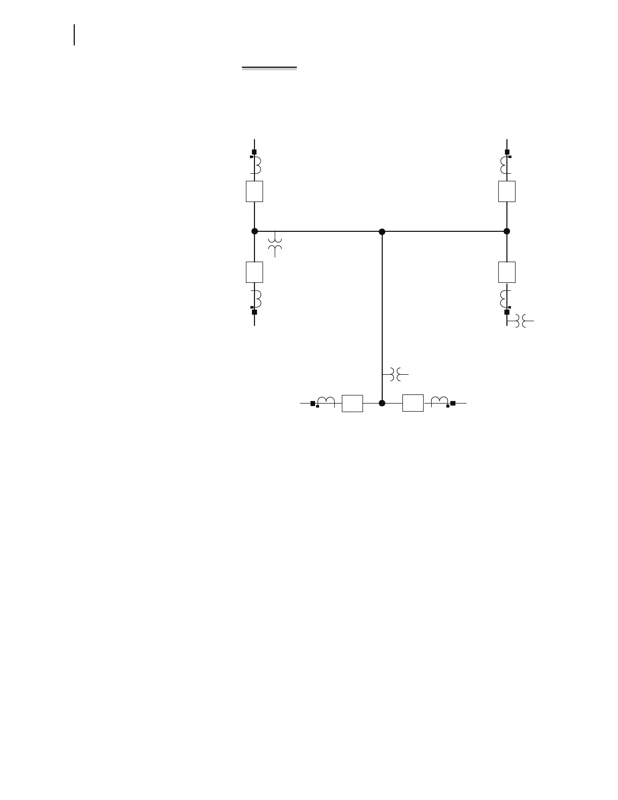
a channel, and open-pole conditions. Assume a three-terminal 3SM
application such as Figure 3.43 shows.
Figure 3.43 Sample Three-Terminal Relay Application
All relays can access voltage signals, and line charging current
compensation is enabled in all three relays. Relays 1 and 3 use line-
side VTs (87CCLPT = L). Relay 2 uses a bus-side VT (87CCLPT = B).
We expect three compensating terminals (87CCN = 3).
Consider the following scenarios:
➤ Normal operation with all breakers closed, no stub bus, and no
LOP conditions, all channels working normally. All three relays
are masters and perform line charging current compensation.
Each relay subtracts a third of the total charging current. As a
result, the charging current calculation is effectively the
average of all three terminal voltages, the best approximation
of the voltage profile along the line. All relays assert 87CCB
(best compensation).
➤ Stub bus condition at Terminal 1. Relay 1 is in the stub bus mode
protecting the bus work between the two local breakers and
the opened line disconnect switch. Relays 2 and 3 protect the
line as far as the opened line disconnect switch at Terminal 1.
Relay 1 ceases to compensate for the charging current. This is a
correct response, because the protected bus work draws no
charging current. Relays 2 and 3 receive a deasserted 87CCC
bit from Relay 1. These relays then determine that there are
two compensating relays, and they switch their multipliers
from 1/3 to 1/2. As a result, the compensation occurs correctly,
but calculation of the charging current is now effectively the
average of voltages at Terminals 2 and 3. This decreases the
compensation accuracy slightly compared with the case that
uses the average of all three terminal voltages—Terminal 1 is
opened, so it may develop an elevated voltage and cause more
charging current. All three relays assert the 87CCD Relay Word
bit, signaling degraded compensation (the compensation uses
the average of two line terminal voltages instead of all three).
Relay Version -1 Relay Version -2
Relay Version -3