P.3.31
Date Code 20151029 Protection Manual SEL-411L Relay
Protection Functions
87L Differential Elements
The relays calculate the base value for the 87L function as the highest CT
primary among the local and remote CTs of the 87L function.
Equation 3.34
where I
NOM
is the nominal secondary current of the relay (5 A or 1 A).
Equation 3.34 uses both W and X local terms only if you have programmed
the associated 87CTWL and 87CTXL SEL
OGIC control equations. The
equation uses the E87CH application setting to apply the actual number of
remote terminals (1, 2, or 3).
The CTBASE value of Equation 3.34 represents a numerical value of 1.0 pu
of the 87L zone, thus defining the meaning of other associated settings such as
the overcurrent pickup thresholds for the 87L elements.
87LP Phase Differential Elements
This section describes the application without in-line transformers
(87XFMR = N). Refer to 87L Differential Applications With In-Line
Transformers if you apply the relay to a line including a power transformer
connected in series.
As Figure 3.19 shows, the phase differential elements apply the three basic
settings of the Alpha Plane characteristic (pickup, radius, and blocking angle
(see Table 3.3) to their operating quantities (magnitude of the differential
current, ratio, and angle of the Alpha Plane (see Table 3.4).
As Table 3.3 shows, the relay provides Alpha Plane settings as normal security
settings and extended security mode settings. The 87L logic switches between
the two sets according to the status of the 87LPSEC Relay Word bit (see
Extended Security Setting Switchover Logic).
CTBASE max 87CTP1R, 87CTP2R, 87CTP3R, CTRW I
NOM
CTRX, I
NOM
=
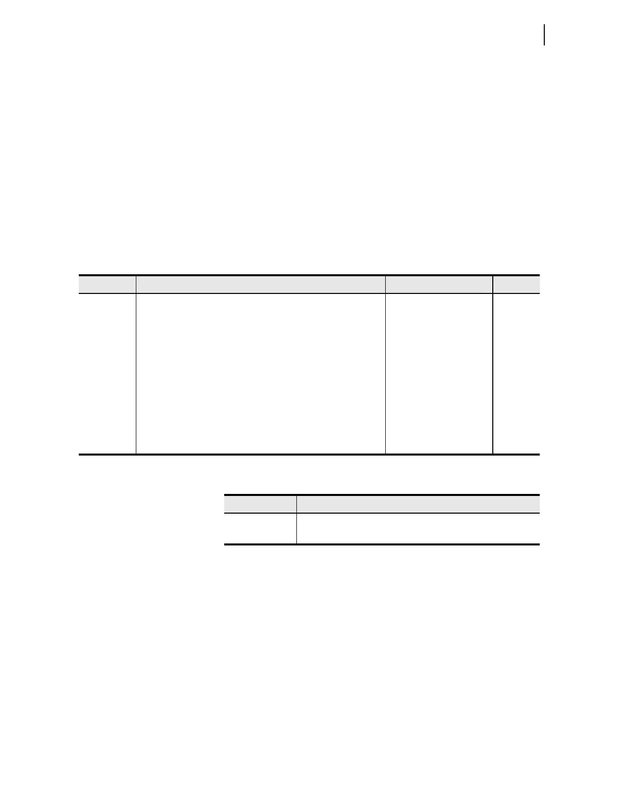
Table 3.1 87L Current Input Configuration Settings
Setting Description Range Default
87CTWL Include current Terminal W as input to the 87L function SELOGIC control equation 1
87CTXL Include current Terminal X as input to the 87L function SEL
OGIC control equation 1
87CTPWL Polarity (P = positive, N = negative) of the terminal W current as an
input to the 87L function
P, N P
87CTPXL Polarity (P = positive, N = negative) of the Terminal X current as an
input to the 87L function
P, N P
87CTP1R CT primary current of the remote Relay 1 1–5000 1000
87CTP2R CT primary current of the remote Relay 2 1–5000 1000
87CTP3R CT primary current of the remote Relay 3 1–5000 1000
87LTAPW
a
a
Read only setting; hidden if E87XFMR = Y or 87CTXL = 0.
CT tap for the current Terminal W 5–50 @ 5 A, 1–10 @1 A 5
87LTAPX
a
CT tap for the current Terminal X 5–50 @ 5 A, 1–10 @1 A 5
Table 3.2 87L Current Input Configuration Relay Word Bits
Name Description
87CTWL Current Terminal W included as input to the 87L function
87CTXL Current Terminal X included as input to the 87L function