P.3.34
SEL-411L Relay Protection Manual Date Code 20151029
Protection Functions
87L Differential Elements
The same internal logic of the Alpha Plane comparator, with adequate
operating quantities and settings, applies to the phase-, negative-, and zero-
sequence differential elements.
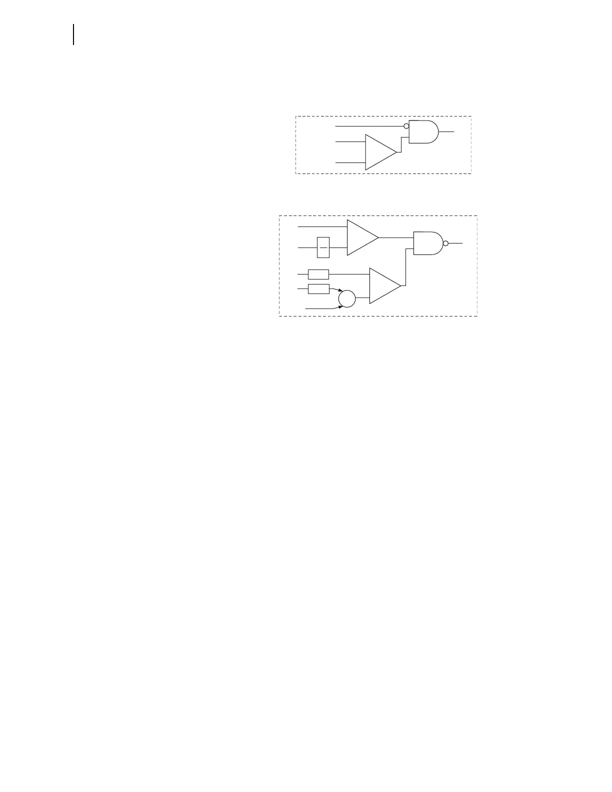
Figure 3.20 Overcurrent Supervision Logic for Line Current Differential
Elements (Use With Logic Diagrams in Figure 3.19, Figure 3.22, and Figure 3.23).
Figure 3.21 Alpha Plane Comparator Logic for Line Current Differential
Elements (Use With Logic Diagrams in Figure 3.19, Figure 3.22, and Figure 3.23).
Detailed Description of Settings
87LPP and 87LPPS
These settings specify the pickup threshold for the phase differential element.
The full-cycle cosine-filtered phase differential current must exceed the level
these settings specify for the element to operate. These settings are in per unit
of the 87L function. In applications without in-line transformers, 1.0 pu is the
highest primary of any CT of the differential zone (see 87L Theory of
Operation for more details).
The extended security setting, 87LPPS, is available under advanced settings
(EADVS = Y). Set this higher to provide better security, as necessary. You
should see a warning message if you attempt to make this setting less than
87LPP. If the advanced settings are disabled, setting 87LPP to a value other
than OFF sets 87LPPS to 1.2 • 87LPP, but no greater than the maximum
setting limit of 2 pu.
Select a pickup setting that ensures security for differential currents not
resulting from internal faults. Considerations may include the following.
➤ Line charging current. The maximum line charging current
should be considered with a safety factor of 2 to 3 to account
for inrush charging current during line energization. Enabling
line charging current compensation allows reduction of the
pickup threshold, improving the element's sensitivity.
➤ Unmeasured tapped loads. Use the maximum current from
unmeasured load taps with a safety factor that accounts for
faults, cold load pickup, and inrush upon line energization.
Such inrush may include magnetizing inrush from transformers
used to tap the load. The relay provides an option to back up
and coordinate with the tapped load phase protection (see Time-
Overcurrent Differential Protection for more details).
-
+
Overcurrent Comparator
PKP = OFF
ID
PKP
OC
–
+
1
x
–
+
Σ
–
+
Alpha Plane Comparator
k
RAD
AP
A
BA
abs
0.5
180°