P.3.249
Date Code 20151029 Protection Manual SEL-411L Relay
Protection Functions
Circuit Breaker Failure Protection
Failure to Interrupt
Fault Current:
Scheme 2
Scheme 2 actually consists of two discrete circuit breaker failure protection
schemes. The first scheme is applied for multiphase faults; apply a short time
delay on pickup prior to asserting the circuit breaker failure trip since three-
phase faults are the greatest threat to transient power system stability. The
second scheme is applied for single phase-to-ground faults; an additional
timer is provided so you can coordinate retripping and circuit breaker failure
tripping for the different fault types.
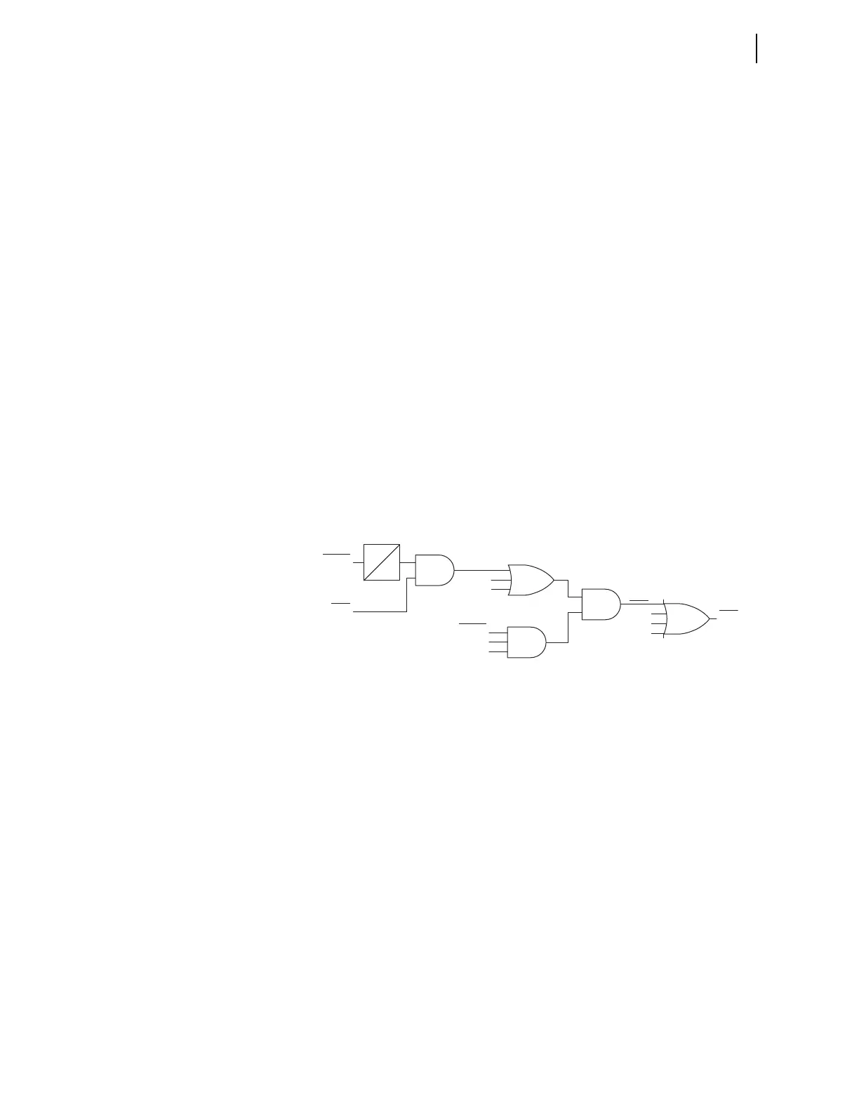
Circuit Breaker Failure Protection Logic: Multiphase Faults
The logic diagram shown in Figure 3.162 applies to three-pole tripping for
one or two circuit breakers. Use this logic when the protected circuit breaker
fails following a three-pole trip from the line-relaying scheme.
Fault current causes 50FA1 (Breaker 1 A-phase instantaneous overcurrent
element) to assert immediately following fault inception and just prior to the
assertion of Relay Word bit BFIA1 (Breaker 1 A-phase circuit breaker failure
initiation). At circuit breaker failure initiation, timer BFPU1 (Breaker 1 circuit
breaker failure time delay on pickup timer) starts timing. If 50FA1 remains
asserted when timer BFPU1 expires and at least two of the three initiation
Relay Word bits BFIA1, BFIB1, or BFIC1 are asserted, Relay Word bit FBF1
(Breaker 1 circuit breaker failure) asserts. (Two of three asserted initiation
Relay Word bits indicate a multi-phase fault.) Use FBF1 in the circuit breaker
failure tripping logic to cause a circuit breaker failure trip (see Circuit Breaker
Failure Trip Logic). If the protected circuit breaker opens successfully, 50FA1
drops out before timer BFPU1 expires and Relay Word bit FBF1 does not
assert.
Figure 3.162 Scheme 2 Three-Pole Circuit Breaker Failure Protection Logic
Circuit Breaker Failure Protection Logic: Single-Phase Faults
The logic diagram shown in Figure 3.163 applies to single-pole tripping for
one or two circuit breakers. A-phase is discussed; B-phase and C-phase logic
is similar. Use this logic when one pole of the circuit breaker fails following a
single-pole trip from the line-relaying scheme.
Fault current causes 50FA1 (Breaker 1 A-phase instantaneous overcurrent
element) to assert immediately following ground fault inception and just prior
to the assertion of Relay Word bit BFIA1 (Breaker 1 A-phase circuit breaker
failure initiation). At circuit breaker failure initiation timer BFPU1 (Breaker 1
circuit breaker failure time delay on pickup timer) starts timing. Timer BFPU1
cascades into timer SPBFPU1 (Breaker 1 single-pole trip breaker failure time
delay on pickup timer). Therefore, use this second timer, SPBFPU1, to
coordinate circuit breaker failure operations for single-pole and three-pole
trips.
If 50FA1 remains asserted when timer SPBFPU1 expires and neither of the
two Relay Word bits BFIB1 and BFIC1 are asserted, Relay Word bit FBFA1
(A-phase Breaker 1 circuit breaker failure) asserts. Use FBFA1 in the circuit
breaker failure tripping logic to cause a circuit breaker failure trip (see Circuit
Breaker Failure Trip Logic). If the protected circuit breaker successfully
FBF1
BFIA1
50FA1
B-Phase
C-Phase
BFIA1
BFIB1
BFIC1
FBFC1
FBFB1
FBFA1
A-Phase
Relay
Word
Bit
Relay
Word
Bit
Relay
Word
Bits
SELOGIC
Settings
SELOGIC
Setting
BFPU1
0
2 of 3