P.3.233
Date Code 20151029 Protection Manual SEL-411L Relay
Protection Functions
Directional Comparison Unblocking Scheme Logic
PTRX1 asserts for loss of channel or for an actual received permissive trip in
two-terminal line applications (e.g., setting ECOMM to DCUB1).
PTRX1 or PTRX2 assert for loss of channel or for an actual received
permissive trip (for the respective Channel 1 or 2) in three-terminal line
applications (e.g., setting ECOMM to DCUB2).
Enable setting ECOMM (when set to DCUB1 and DCUB2) determines the
routing of Relay Word bits PTRX1 and PTRX2 to control Relay Word bit
PTRX. Relay Word bit PTRX is the permissive trip receive input into the trip
logic.
Three-Terminal Lines
If you apply the DCUB scheme to a three-terminal line, program SELOGIC
control equation PT1 and PT2 as follows:
PT1 := IN205 General permissive trip received (SELOGIC equation)
PT2 := IN206 Channel 2 permissive trip received (SELOGIC equation)
Relay control inputs IN205 or IN206 assert when the relay receives a
permissive signal from one of the two other terminals. The relay cannot high-
speed trip until both inputs assert. These two control inputs were chosen for
this example. Use control inputs that are appropriate for your application.
In addition, for a three-terminal line, program SEL
OGIC control equations
LOG1 and LOG2 as follows:
LOG1 := IN205 Channel 1 loss-of-guard
LOG2 := IN206 Channel 2 loss-of-guard
Relay control inputs IN205 or IN206 assert when the relay receives a loss-of-
guard signal from either of the two other terminals. When SEL
OGIC control
equation LOG1 (Channel 1 loss-of-guard) asserts, the relay asserts Relay
Word bit UBB1 (block permissive trip on Receiver 1) and removes the
possibility that Relay Word bit PTRX1 (permissive trip on Receiver 1) will
assert. These two control inputs were chosen for this particular example. Use
control inputs that are appropriate for your application.
See Table 3.121 for the DCUB settings. The first portion of the settings (from
Z3RBD to PT1) are identical to the settings for the ECOMM := POTT scheme
(see POTT Scheme Logic).
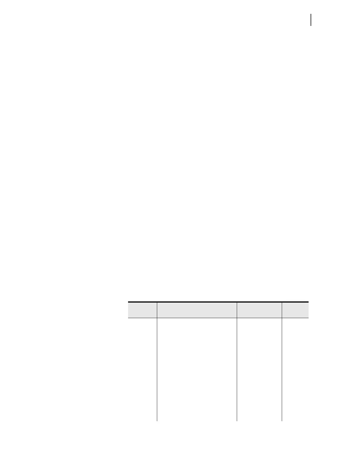
Table 3.121 DCUB Settings (Sheet 1 of 2)
Setting Description Range
Default
(5 A)
Z3RBD Zone 3 reverse block time delay
(cycles)
0.000–16000 5.000
EBLKD Echo block time delay (cycles) 0.000–16000 10.000
ETDPU Echo time delay pickup (cycles) 0.000–16000 2.000
EDURD Echo duration time delay (cycles) 0.000–16000 4.000
EWFC Weak infeed trip Y, N, SP N
27PWI
a
Weak infeed phase undervoltage
pickup (V)
1.0–200 47.0
27PPW
b
Weak infeed undervoltage pickup
(V
)
0.1–300 80.0
59NW
b
Weak Infeed zero-sequence
overvoltage pickup (V)
0.1–200 5.0
PT1 General permissive trip received SEL
OGIC equation NA