P.3.49
Date Code 20151029 Protection Manual SEL-411L Relay
Protection Functions
87L Differential Elements
87L User-Programmable Bits Over Serial Channels
SELOGIC control equations drive the transmitted user-programmable 87L
communications bits, 87TnPp, per Table 3.17 (where n enumerates the
transmitted bit, n = 1–4; p stands for the serial port, p = 1 or 2). An associated
Relay Word bit with the same label as the setting 87TnPp, per Table 3.17,
signals assertion of the transmitted 87L communications bit. In other words, if
SEL
OGIC control equation 87T1P1 (Table 3.17) asserts, then the Relay Word
bit 87T1P1 (Table 3.17) also asserts. The SEL
OGIC control equations for the
communications bits (87TnPp) are located in the Output settings. The E87PG
setting (E87PG = G) located in the PORT 87L Settings class can relocate
these settings to the Group settings to allow different bits to be transmitted
based on the settings group enabled (see Table 3.133). These settings will be
automatically hidden if the hardware does not support 87L serial
communications or if the setting E87CH = N.
The corresponding received user-programmable 87L communications bits
map to Relay Word bits, 87R0nPp, per Table 3.17. Per Table 3.17, each
received bit has a debounce timer with independent pickup (87RnpPU) and
dropout (87RnpDO) settings.
You can use the pickup timer to enhance security in applications over noisy
channels (see Security of 87L User-Programmable Communications Bits).
You can use the dropout timer to ensure dependable recognition of the bit,
given the assertion period we can expect at the sending relay and details of the
application logic at the receiving relay.
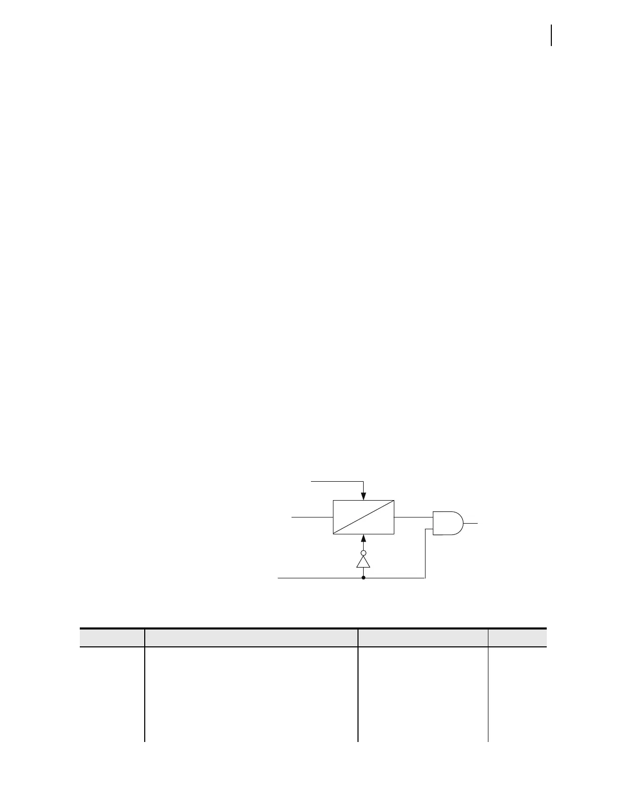
The relay implements the debounce timer and the fail-safe values as
Figure 3.27 shows. If the relay receives an invalid packet, the timer stalls.
Subsequently, when the 87CHpOK Relay Word bit deasserts, the timer resets,
and the relay substitutes logic 0 for the received bit. When the channel
recovers and the 87CHpOK Relay Word bit asserts, the relay releases the
timer from the reset state, and the received bit passes normally through the
timer to drive the 87R0nPp Relay Word bit.
Figure 3.27 Interaction Between Debounce Timing and Fail-Safe
Substitution in the User-Programmable 87L Bits Logic
Invalid packet
received, or packet
timed-out
n-th bit in the packet,
p-th channel
Relay Word Bit
87CHpOK
STALL
87RnpPU
87RnpDO
Relay Word Bit
87ROnPp
RESET
Table 3.17 87L User-Programmable Communications Bits Settings (Serial Channels) (Sheet 1 of 2)
Setting Description Range Default
87T1P1 Bit 1 transmitted on Serial Port 1 SELOGIC control equation NA
87T2P1 Bit 2 transmitted on Serial Port 1 SEL
OGIC control equation NA
87T3P1 Bit 3 transmitted on Serial Port 1 SEL
OGIC control equation NA
87T4P1 Bit 4 transmitted on Serial Port 1 SEL
OGIC control equation NA
87T1P2 Bit 1 transmitted on Serial Port 2 SEL
OGIC control equation NA
87T2P2 Bit 2 transmitted on Serial Port 2 SEL
OGIC control equation NA