P.3.46
SEL-411L Relay Protection Manual Date Code 20151029
Protection Functions
87L Differential Elements
87DTT Direct Transfer Tripping Logic
The 87L function within the relay provides dedicated direct transfer tripping
(87DTT) over the 87L communications channels; this direct transfer tripping
is not the conventional unsupervised tripping of a circuit breaker from a
remote condition.
More specifically, this tripping logic applies to three-terminal applications
over serial channels. In these applications, two of the three relays can become
slaves if a communications channel fails, cannot be synchronized properly, or
is not installed. In this situation, the third relay can operate as a master, and the
87L function in this relay will assert an output for internal faults. The 87DTT
logic sends the 87L outputs to the remote 87L elements to ensure tripping of
the outstation relays for this situation.
The default 87DTT logic does not operate in two-terminal applications, in
which both relays must serve as masters otherwise the 87L function is lost
entirely. Please note that in special cases where DTT logic would normally be
used (e.g. a breaker open at one line end) the 87L disturbance detector has a
low current detector which will activate it's local disturbance detector and also
the remote disturbance detector of the relay at the other line end. Should a
fault occur, the relay with the breaker open will see the differential current and
also be accompanied by the disturbance detector and will issue a trip signal,
no direct transfer tripping logic necessary.
In a three- or four-terminal Ethernet application, if the relay is not a master
and the direct transfer trip function is enabled (E87DTT = 1), the trip logic
(see Figure 3.153) will assert based on receipt of the direct trip signal from
any one of the remote relays.
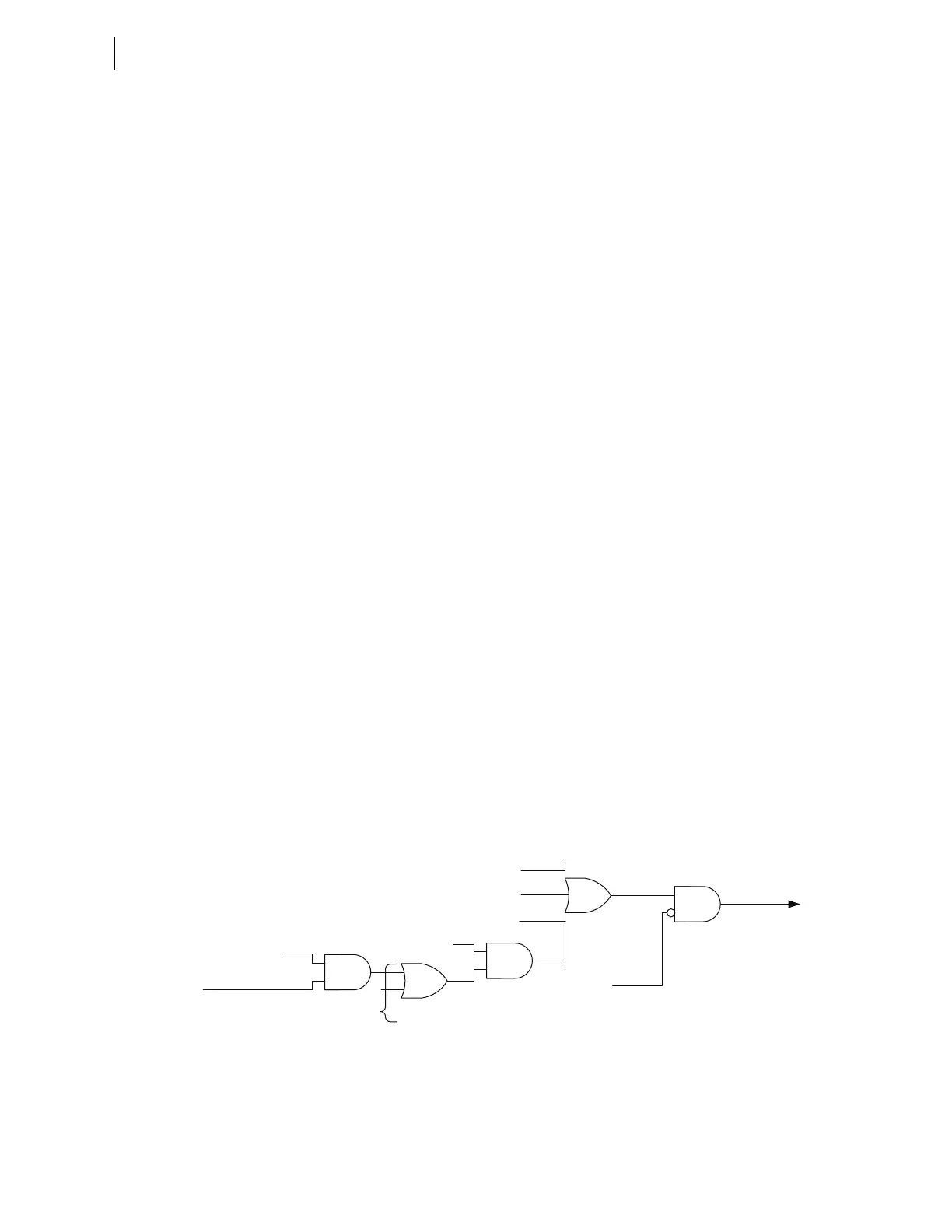
As Figure 3.25 shows, the 87L logic always transmits the 87DTT bit in the
87L data packets. The logic forces the bit to 0 if the relay is in the stub bus,
because there should be no tripping of the line for faults in the bus work
between the line CT (or CTs) and the opened disconnect switch (see Stub Bus
Condition for more details). Operation of the phase, negative-sequence, and
zero-sequence elements always drives the transmitted bit. In addition, the
logic allows keying of the 87DTT bit from the time-overcurrent elements
configured to work with the differential current in applications with tapped
and unmeasured loads (see Time-Overcurrent Differential Protection for more
details). The selectable time-overcurrent elements can key from their 51Txx
Relay Word bits, if you set their operating quantity, 51Oxx, to a differential
current and set the E51DTT setting to Y.
Figure 3.25 87DTT Transmit Logic
51Oxx =
87LAFM, or 87LBFM,
or 87LCFM, or 87L1FM,
or 87LQFM, or 87LGFM
Relay Word Bit
51Txx
xx = 01–10
Setting
E51DTT = Y
Relay Word Bits
87LP
87LQ
87LG
Relay Word Bit
ESTUB
87DTT bit to all
remote terminals
Setting