P.10.3
Date Code 20151029 Protection Manual SEL-411L Relay
Basic Relay Operations
Connecting and Applying Power
Connecting and Applying Power
Connect external power to the relay to perform the initial checkout and
familiarization procedures in this section. For complete information on power
connections, see Power Connections on page P.2.32.
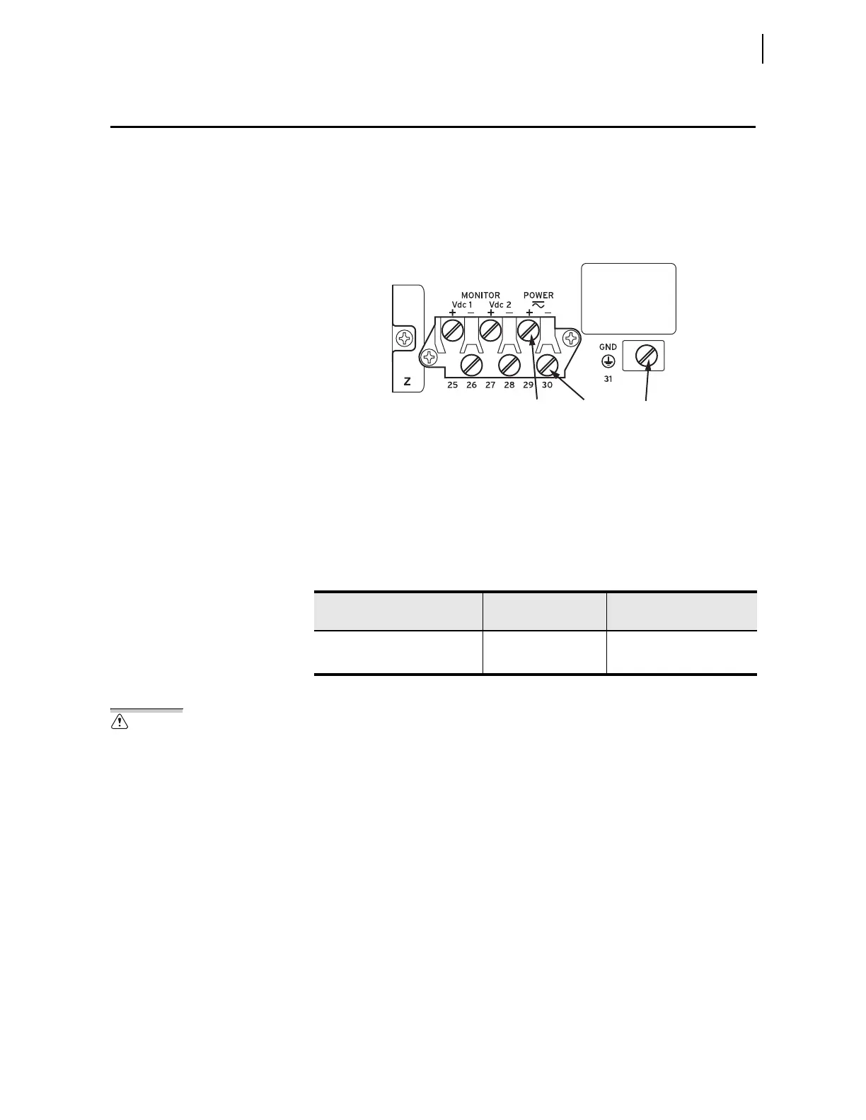
Figure 10.2 shows the portion of the relay rear panel where you connect the
power input.
Figure 10.2 Power Connection Area of the Rear Panel
You can order the relay with one of two power supplies with nominal
operating voltages: 48–125 Vdc, and 125–250 Vdc. The relay serial number
label on the back of the relay lists voltage ranges that encompass the nominal
voltages.
Table 10.1 shows the power-supply rated and operational-voltage ranges for
the dc and ac inputs.
Observe the following precautions when connecting power to the relay:
Contact with instrument terminals can
cause electrical shock that can result
in injury or death.
Step 1. Always attach a safety ground as the first connection you make
to the relay.
Step 2. Connect the grounding terminal (#Z31) labeled GND on the rear
panel to a rack frame ground or main station ground for proper
safety and performance.
Step 3. Use 16 AWG (1.5 mm
2
) wire (or heavier) to connect to the
POWER terminals, observing the following:
➤ When you use a dc power source, you must connect the source
with the proper polarity, as indicated by the + (Terminal #Z29)
and – (Terminal #Z30) symbols on the power terminals.
➤ You can use ac input for the 48/125 Vdc power supply and the
125/250 Vdc power supply.
Table 10.1 Power Supply Voltage Inputs
Rated Voltage
DC Operational
Voltage Range
AC Operational Voltage
Range (30—120 Hz)
48–125 Vdc or 110–120 Vac 38–140 Vdc, <35 W 85–140 Vac, <90 VA
125–250 Vdc or 110–240 Vac 85–300 Vdc, <35 W 85–264 Vac, <90 VA
Terminal Z29 Terminal Z30 Terminal Z31
Serial
Number
Label