P.3.194
SEL-411L Relay Protection Manual Date Code 20151029
Protection Functions
Quadrilateral Phase Distance Elements
If Equation 3.89 is not satisfied, use Equation 3.90 to determine the negative-
sequence nonhomogeneity.
Equation 3.90
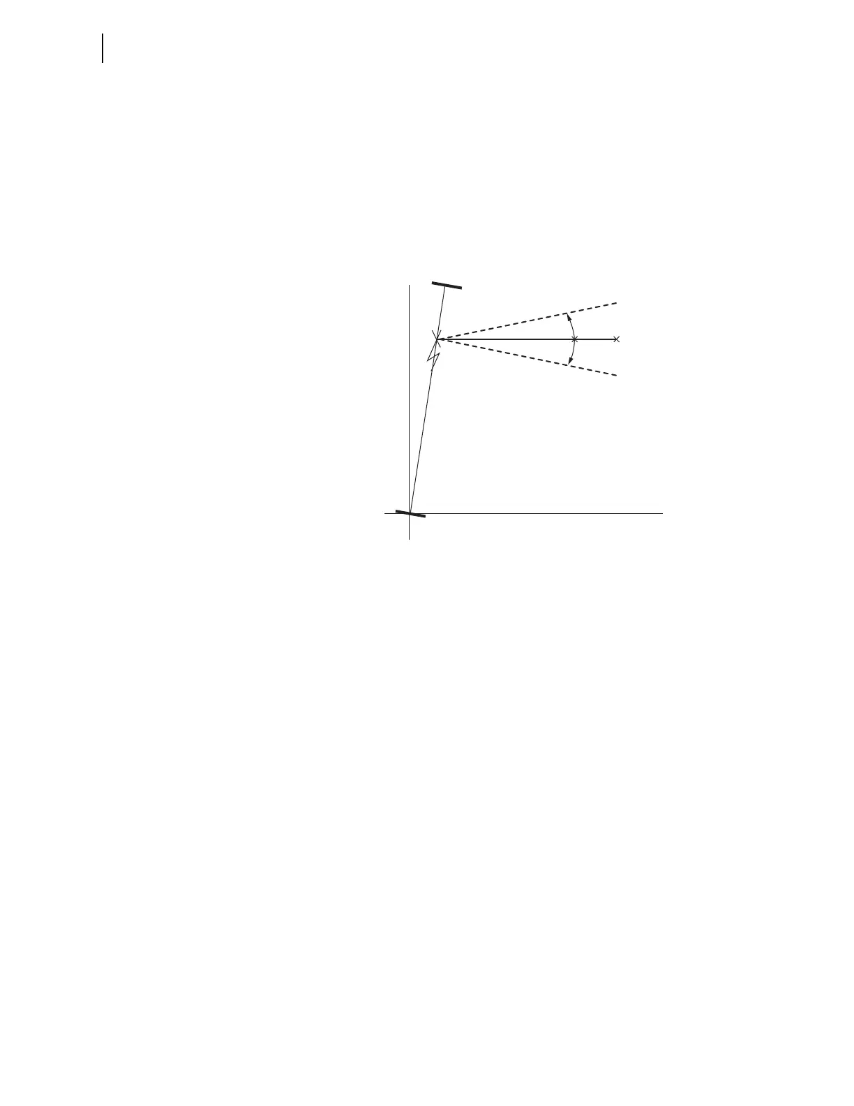
The value of T represents how much the apparent fault impedance (ZF)
measured by the relay tilts up or down (electrical degrees) because of the
nonhomogeneity of the corresponding network for a fault at location m (see
Figure 3.133).
Figure 3.133 Tilt in Apparent Fault Impedance Resulting From
Nonhomogeneity
Calculate T for a phase-to-phase fault at the remote bus (i.e., m equals one per
unit). The remote bus is selected for the fault location to prevent Zone 1 phase
distance element overreach.
Each quadrilateral phase-distance element is supervised by the corresponding
Relay Word bit ENX2AB, ENX2BC, or ENX2CA during unbalanced fault
conditions (32QE = 1). This supervisory condition secures the reactance
element in the quadrilateral phase-distance element against unusual
unbalanced load conditions where the currents are unbalanced but not the
voltages.
A supervisory condition is applied to force the right-resistive blinders to be
self polarized under the above unusual unbalanced loads. The adaptability of
the positive-sequence polarized resistive blinder is enabled during balanced
operating conditions (32QE = 0). This adaptability is also enabled during
unbalanced fault conditions (32QE = 1) when the corresponding Relay Word
bit CNR1AB, CNR1BC, or CNR1CA is asserted. The adaptability of the
negative-sequence polarized resistive blinder is enabled during unbalanced
fault conditions (32QE = 1) when the corresponding Relay Word bit CNR2AB,
CNR2BC, or CNR2CA is asserted. When the adaptability of any of the right
resistive blinders is disabled the corresponding blinder uses self polarization.
Table 3.98 shows the enable, reach, and directional settings for the
quadrilateral phase distance elements. When you set the number of zones you
want to enable (E21XP), this setting applies to both the high-speed and
conventional elements. For example, E21XP = 2 makes two zones (Zone 1 and
Zone 2) available for both the high-speed and conventional elements and hides
the remaining zones.
T
Z1S Z1L Z1R++
1m–Z1L Z1R+•
-----------------------------------------------------
arg=