P.2.9
Date Code 20151029 Protection Manual SEL-411L Relay
Installation
Shared Configuration Attributes
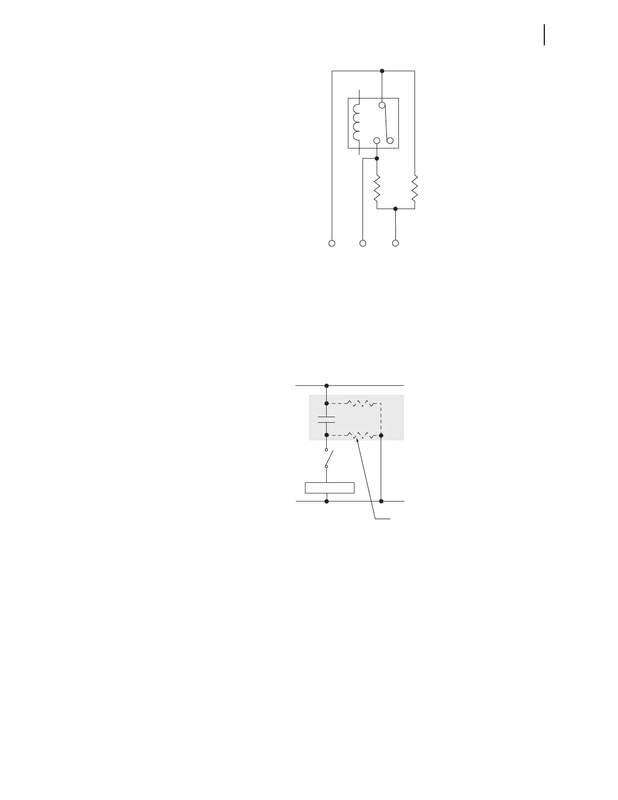
Figure 2.7 High-Speed, High-Current Interrupting Control Output Typical
Te r m i n a l s, I N T E
Figure 2.8 shows some possible connections for this third terminal that will
eliminate the false pick-up transients when closing an external switch. In
general, you must connect the third terminal to the dc rail (positive or
negative) that is on the same side as the open external switch condition. If an
open switch exists on either side of the output contact, then you can
accommodate only one condition because two open switches (one on each
side of the contact) defeat the precharge circuit.
Figure 2.8 Precharging Internal Capacitance of High-Speed, High-Current
Interrupting Output Contacts, INTE
For wiring convenience, on the INTE I/O Interface Board, the precharge
resistors shown in Figure 2.7 are built-in to the I/O board, and connected to a
third terminal. On the INTC I/O Interface Board, there are no built-in
precharge resistors, and each high-speed, high-current interrupting control
output has only two terminal connections.
TIME Inputs
The relay has a regular IRIG timekeeping mode, and a high-accuracy IRIG
(HIRIG) timekeeping mode. The IRIG-B serial data format consists of a
1-second frame containing 100 pulses divided into fields, from which the
relay decodes the second, minute, hour, and day fields and sets the internal
time clock upon detecting valid time data in the IRIG time mode. There is one
IRIG-B input on the relay rear panel, capable of supporting the HIRIG mode
(also see Figure 2.16).
Load
(+)
(–)
Precharge Circuit
Path Internal to High-Speed,
High-Current Interrupting
Control Output
01
02 03