P.12.35
Date Code 20151029 Protection Manual SEL-411L Relay
Bay Control
ACSELERATOR QuickSet SEL-5030 Software Bay Control Screens
Click on analog display label MDELE1 in the interactive one-line diagram to
display the form shown in Figure 12.24. Click the Expression Builder button
to the right of the dialog box to display the form in Figure 12.25. The
Expression Builder helps create the analog quantity setting string. Click the
Expression Builder button on the form in Figure 12.25 to cause the analog or
fixed element to be displayed.
Figure 12.24 Analog Quantity Setting Form
To display fixed text instead of analog quantities, enter the number 1 in the
Analog or Fixed Element field, as shown in Figure 12.25. All other fields,
except the Pre-Text field, will be grayed out and no longer accessible.
Figure 12.25 Analog Quantity Setting Form
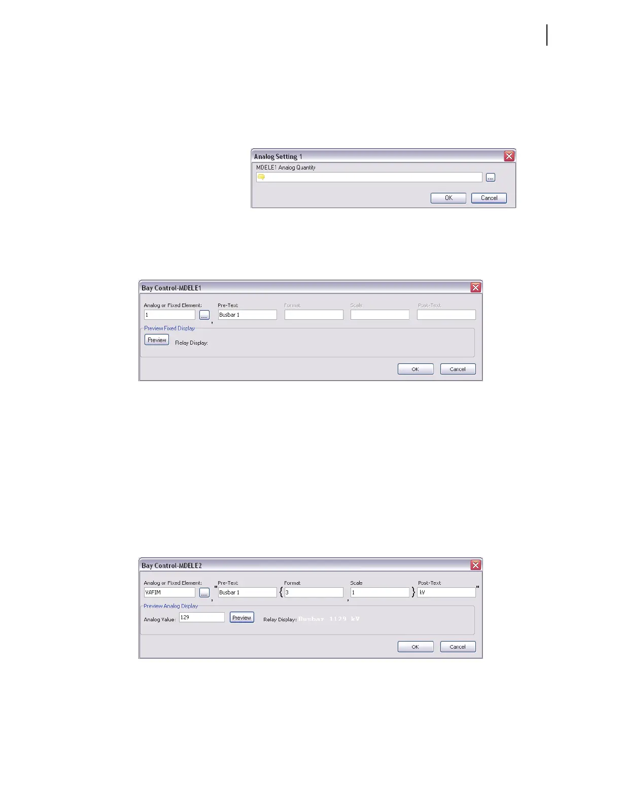
Click on MDELE2 to enter the next analog value. For MDELE2, select the
VAFIM, the A-phase voltage magnitude, as shown in Figure 12.26. Assuming
that the PT is connected to Busbar 1, enter Busbar 1 as the Pre-Text name.
Because the maximum voltage on a 132 kV system will not exceed 999 kV,
enter 3 in the format field (specify three digits to be displayed on the HMI).
You can scale the numerical value of VAFIM to display a scaled value of the
analog quantity. For example, a scaling factor of 0.5 displays only half the
value of VAFIM, while a scaling factor of 2 displays twice the value of
VAFIM. Enter text, such as units of the analog quantity, in the Post-Text field.
Enter a value (129 in this example) in the Analog Value field, click the
Preview button, and verify that all entries are correct and will fit on the
screen.
Figure 12.26 Analog Quantity Expression MDELE2
For the third analog quantity, choose the A-phase line current, and enter the
other information as shown in Figure 12.27. Again, use the Preview button to
verify that all entries are correct and will fit on the screen.