P.3.293
Date Code 20151029 Protection Manual SEL-411L Relay
Protection Functions
87L Channel Monitoring and Alarming Logic
network, when switching paths, corrupts at least one 87L packet. The logic of
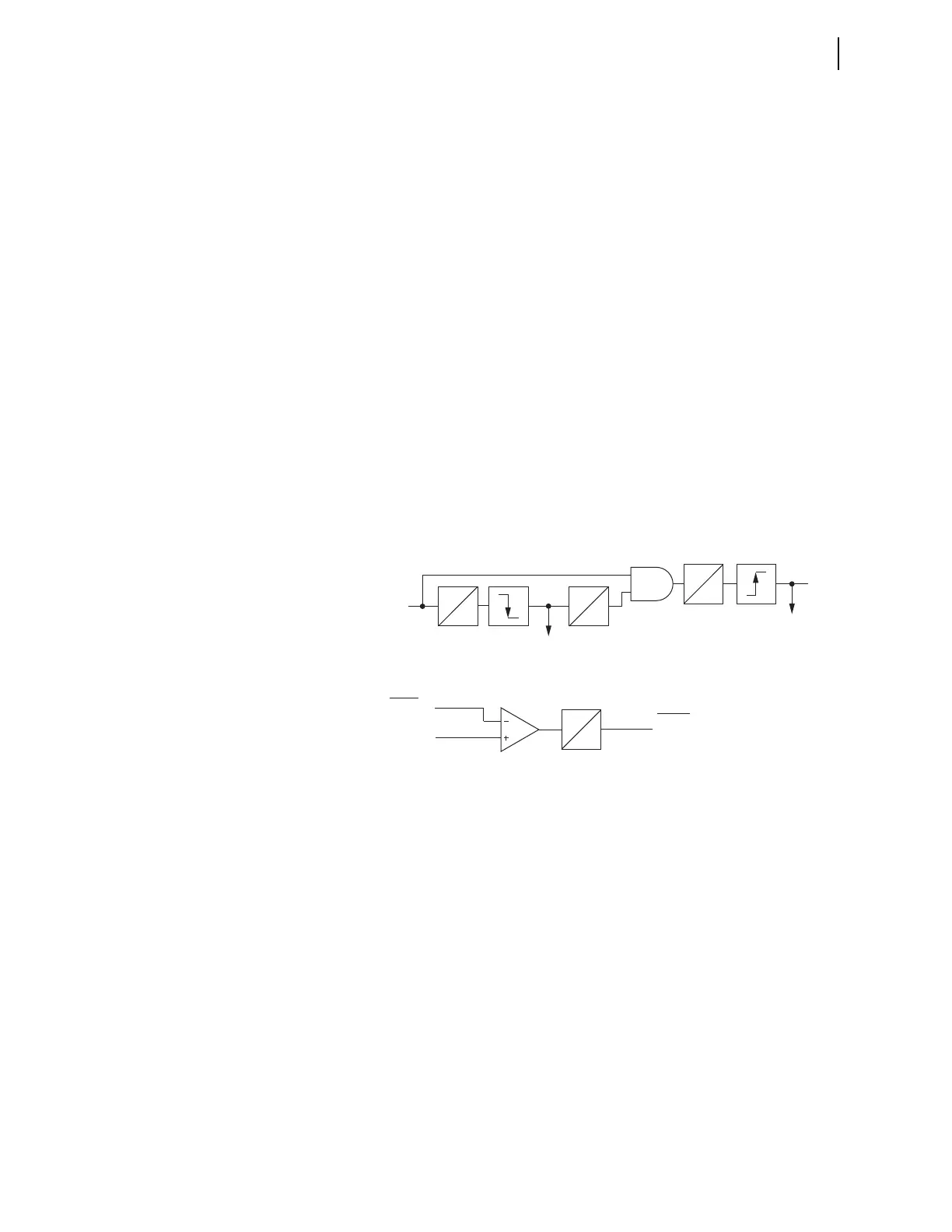
Figure 3.201 triggers for all channel interruptions and checks for the
difference in the round-trip delay measurements. First, the channel must work
properly for a half second before the logic engages. If the 87CHpRT
measurement is invalid after that time, as in the case of a lost packet, the relay
captures the old value of the 87CHpRT and opens a 1-second window to wait
for measurements to resume. If the measurements resume within a second, the
relay captures the new value and calculates the difference (87CHpMDRT).
The relay adds an extra 0.1 s delay to flash out any packets that may be
trapped in communication gear buffers. For channel interruption other than
switching, the logic triggers, but the difference in the round-trip delay
calculates as zero.
Apply the 87CHpMD setting on a per-channel basis to monitor step change in
the round-trip delay. The 87CHpDT Relay Word bit signals an alarm. This bit
stays asserted for 0.1 s. If necessary, use a SEL
OGIC timer to extend bit
assertion.
Note that the time fallback Mode 4 responds to the step change in the round
trip delay measurement, but it uses its own factory-selected threshold and is
independent from the user setting 87CHpMD.
As with the round-trip delay measurement itself, the step change in the round-
trip delay measurement applies to serial channels only and works with or
without external time sources connected to the relays at both ends of a given
channel.
Figure 3.201 Step Change in Round-Trip Delay Logic
Channel Asymmetry
This section applies to serial 87L channels only and to relays connected to
external time sources. Channel asymmetry is only calculated if the relay is set
to time-based synchronization (87CHpSN = T). The channel asymmetry
calculation is suppressed if the relay is set to channel-based synchronization
(87CHpSN = C).
If valid time sources are connected to both relays of a given communication
channel, it is possible to measure not only the round-trip time but the channel
latency in the receiving and transmitting directions individually. In addition,
the relay calculates the difference between the delays in the two directions,
known as channel asymmetry (see 87L Theory of Operation).
Channel asymmetry is an important channel attribute. A typical consideration
is related to using symmetrical channels in the 87L channel-based
synchronization mode. This application is often considered superior because it
requires no external time sources as a part of the protection scheme. Instead,
the channel must be symmetrical to facilitate channel-based synchronization.
Channel-based synchronization works accurately as long as the channel is
truly symmetrical. Often, time sources are connected to relays to allow precise
time stamping for events and records. If the time sources are connected, the
0
0.1 s
0.5 s
0
0
1 s
0.1 s
0
Setting
Relay
Word Bit
87CHpMD
Step change in the
87CHpMDRT
87CHpRT
measurement
valid
87CHpDT
Capture the
“old” value of
87CHpRT
Capture the “new”
value of 87CHpRT
and calculate the
step change