P.3.262
SEL-411L Relay Protection Manual Date Code 20151029
Protection Functions
87L Communication and Timing
An outstation relay does not receive data, but transmits its local data to the
master. Because the outstation does not receive data, it cannot independently
arrive at a trip decision. Instead, it trips its local breaker(s) when commanded
by the master. In two-terminal (serial or Ethernet) and four-terminal (Ethernet
only) applications, all relays are designated masters.
In three terminal applications, depending on the availability of channels, all
relays may be designated masters or there may be one designated master and
two designated slaves. If all relays are designated masters, this application can
tolerate the loss of one of the channels. In such a case, the scheme continues to
function in the master/outstation application. Figure 3.175 shows a
master/outstation application.
Figure 3.175 EIA-422 Three-Terminal, Master/Outstation Serial Application
Using SEL-3094 Interface Converters
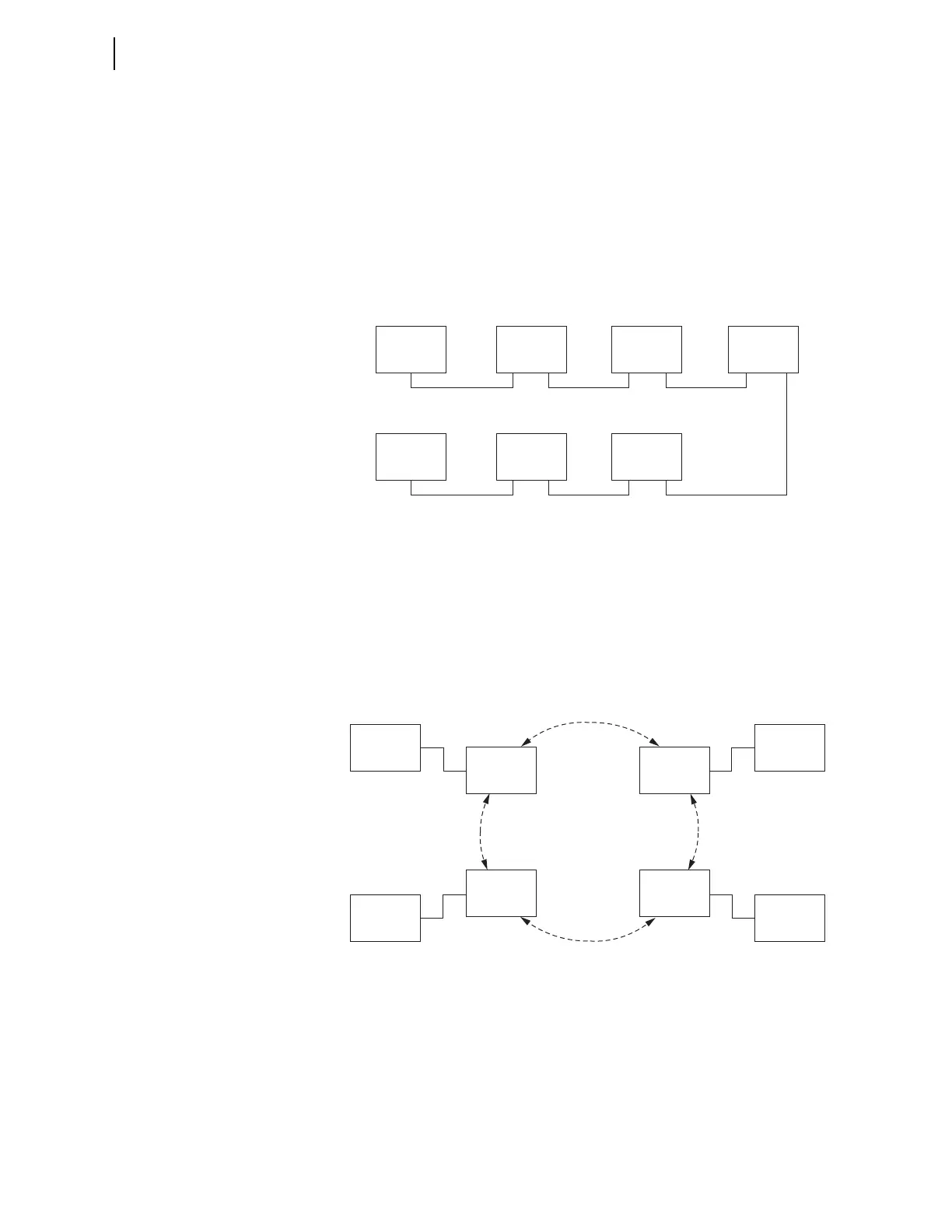
Serial channels are not practical in applications where there are more than
three relays. Consequently, the relay provides a switched packet Ethernet
interface for 87L data exchange. The relay transmits 87L data in the form of a
multicast message. Each message is forwarded to all relays on the network
that are part of the differential scheme. Therefore, each relay needs a single
Ethernet port regardless of the number of relays in the scheme. Figure 3.176
shows a four-terminal application using SEL ICON multiplexers.
Figure 3.176 Four-Terminal Ethernet Application Using SEL ICON Multiplexers
In a two-terminal application with two available channels, these channels can
be used in a redundant mode. The relay reads the remote currents from the
primary channel indicated by the 87PCH setting as long as this channel is
working and allows high-quality current data alignment. Upon the loss of the
primary channel, if the other channel is working or is of better synchronization
quality, the relay switches over to the other channel. Figure 3.177 shows a
two-terminal serial application with redundant channels.
Relay (1)
Slave
Relay (3)
Slave
SEL-3094 (1)
EIA-422
EIA-422
EIA-422
EIA-422
Fiber
Fiber
SEL-3094 (4)
SEL-3094 (2)
SEL-3094 (3)
Relay (2)
Master
Relay (1)
SEL ICON
Multiplexer (1)
Ethernet
SONET Ring
Relay (2)
SEL ICON
Multiplexer (2)
Ethernet
Relay (3)
SEL ICON
Multiplexer (3)
Ethernet
Relay (4)
SEL ICON
Multiplexer (4)
Ethernet