P.3.82
SEL-411L Relay Protection Manual Date Code 20151029
Protection Functions
87L Differential Elements
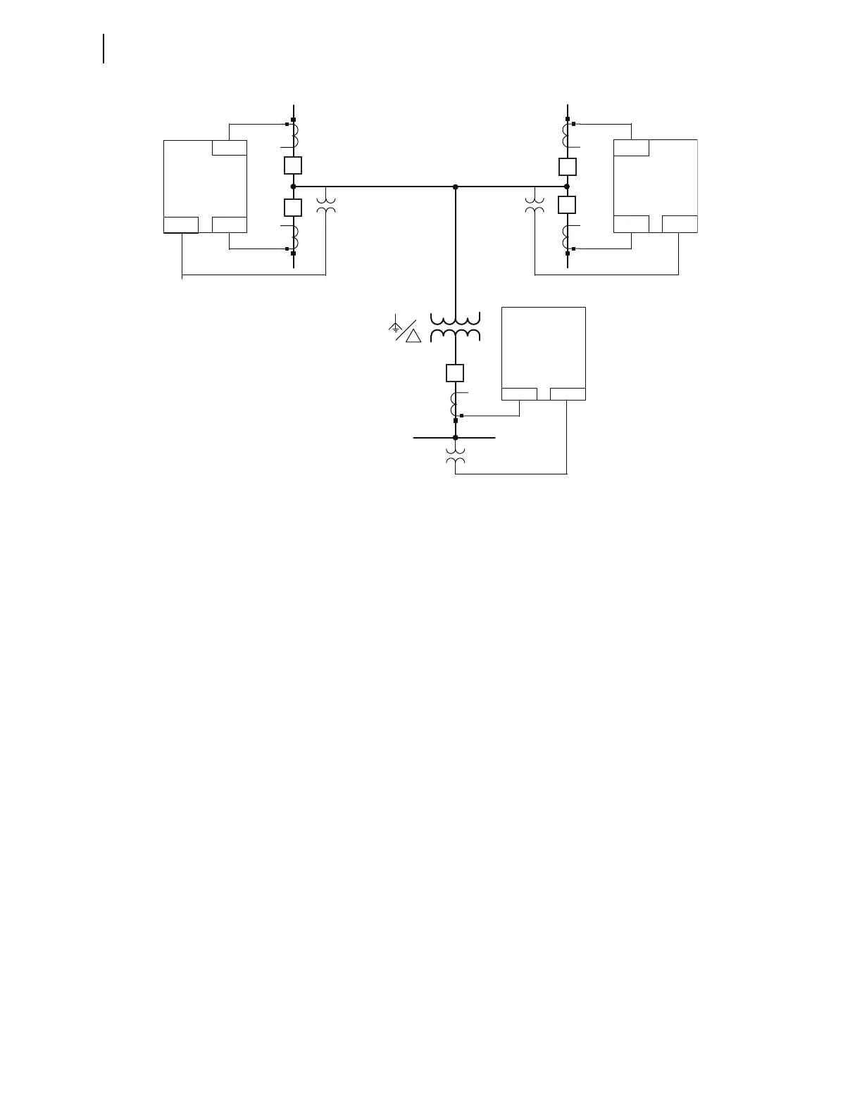
Figure 3.44 Sample Three-Terminal Relay Application With In-Line Transformer
87VTWL and 87VTXL
These settings specify the rated phase-to-phase voltage of the transformer
windings associated with the current input terminals, W and X respectively.
The relay uses this setting to calculate correct tap compensation values for the
87L currents.
Note that, in general, the W and X current input terminals of the relay may be
associated with different windings such as when protecting three-winding
transformers. Or, with the same winding such as when a transformer winding
is terminated in a dual-breaker arrangement, and breaker CTs are used rather
than a transformer bushing CT. Also note that the winding associated with a
given current input terminal of the relay may be located at the remote station
where the power transformer is installed.
Consider the example shown in Figure 3.44. Both the W and X current
terminals of Relay 1 are associated with the 240 kV wye-connected winding
of the transformer, resulting in 87VTWL = 240 kV and 87VTXL = 240 kV.
Both the W and X current terminals of Relay 2 are associated with the same
winding of the transformer, resulting in 87VTWL = 240 kV and
87VTXL = 240 kV at the second relay. Relay 3 is a single-CT application
using the W current input terminal. This current terminal is associated with
the 138 kV delta-connected winding of the transformer resulting in
87VTWL = 138 kV at the third relay.
Note that these settings do not imply the winding voltage is actually measured
by the relay. These settings are used for tap calculations.
87CTCWL and 87CTCXL
These settings specify the compensation matrix (0–12) for the currents of the
W and X relay input terminals, respectively. Note that the two current input
terminals of the relay may be associated with the same or different windings,
IW VY
Relay (2)
Relay (1)
Relay (3)
IW
IX VY
IW
IXVY
1200:5
1200:5
1000:5
1000:5
1000:5
200MVA
240 kV
138 kV