P.4.49
Date Code 20151029 Protection Manual SEL-411L Relay
Autoreclosing and Synchronism-Check
Synchronism Check
Synchronism Check
Synchronism-check elements prevent circuit breakers from closing if the
corresponding phases across the open circuit breaker are excessively out of
phase. The synchronism-check elements selectively close circuit breaker poles
under the following criteria:
➤ The systems on both sides of the open circuit breaker are in
phase (within a settable voltage angle difference).
➤ The voltages on both sides of the open circuit breaker are
healthy (within a settable voltage magnitude window).
You can use synchronism-check elements to program the relay to supervise
circuit breaker closing; include the synchronism-check element outputs in the
close SEL
OGIC control equations. These element outputs are Relay Word bits
25W1BK1, 25A1BK1, 25W2BK1, 25A2BK1, 25W1BK2, 25A1BK2,
25W2BK2, and 25A2BK2 (see Synchronism-Check Logic Outputs and Angle
Checks and Synchronism-Check Element Outputs).
An example best demonstrates the synchronism-check capability in the relay.
This subsection presents a typical synchronism-check system.
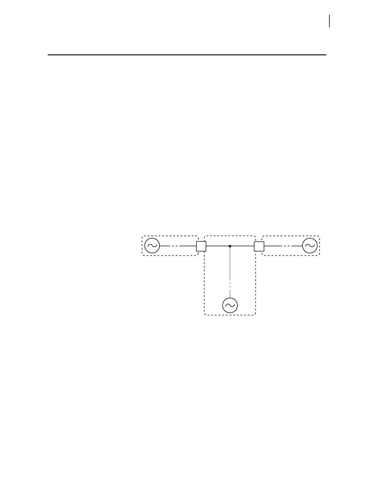
Generalized System
The generalized system single-line drawing in Figure 4.19 shows a partial
circuit breaker-and-a-half or ring-bus substation arrangement. Presuming that
both Circuit Breakers BK1 and BK2 are open, the system is split into three
sections: Bus 1, Bus 2, and Line.
Figure 4.19 Partial Breaker-and-a-Half or Partial Ring-Bus Breaker
Arrangement
Paralleled and
Asynchronous
Systems
Figure 4.19 shows remote sources for each section. Often, a portion of the
power system is paralleled beyond the open Circuit Breakers BK1 and BK2;
the remote sources are really the same aggregate source. If the aggregate
source is much closer to one side of the open circuit breaker than the other,
there is a noticeable voltage angle difference across the system (it is not
simply zero degrees). The corresponding angular separation results from load
flow and the impedance of the parallel system.
You must consider this angle difference when setting the synchronism-check
element for a paralleled system. For example, if the expected angle because of
load flow is 10 degrees, do not set the voltage angle difference setting to less
than 15–20 degrees nominal. A paralleled system does not imply a zero degree
voltage angle difference at every measuring point.