P.3.138
SEL-411L Relay Protection Manual Date Code 20151029
Protection Functions
Loss-of-Potential Logic
Setting ELOP := Y
If you set ELOP to Y and an LOP condition occurs, the voltage-polarized
directional elements and all distance elements are disabled. The forward-
looking directional overcurrent elements effectively become nondirectional
and provide overcurrent protection during an LOP condition.
Setting ELOP := Y1
If you set ELOP to Y1 and an LOP condition occurs, the voltage-polarized
directional elements and all distance elements are disabled. This setting for
ELOP also disables the overcurrent elements that these voltage-polarized
directional elements control.
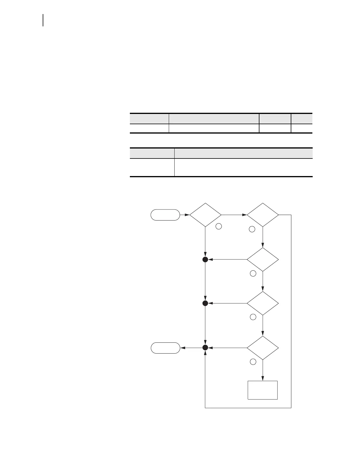
Figure 3.81 illustrates how the LOP logic processes an LOP decision.
Figure 3.82 provides a logic diagram for the LOP logic.
Figure 3.81 LOP Logic Process Overview
Table 3.69 LOP Logic Setting
Name Description Range Default
ELOP Loss-of-potential Y, Y1, N Y1
Table 3.70 LOP Logic Relay Word Bits
Name Description
ILOP Internal loss-of-potential from ELOP setting
LOP Loss-of-potential detected
START
|V1|
decreasing?
∠
I1
changing?
|I1|
changing?
|3I0|
changing?
END
Declare
LOP
2
1
3
4
Y
Y
YY
N
N
N
N
5
Y
N
∠
3I0
changing?