P.3.182
SEL-411L Relay Protection Manual Date Code 20151029
Protection Functions
Quadrilateral Ground-Distance Elements
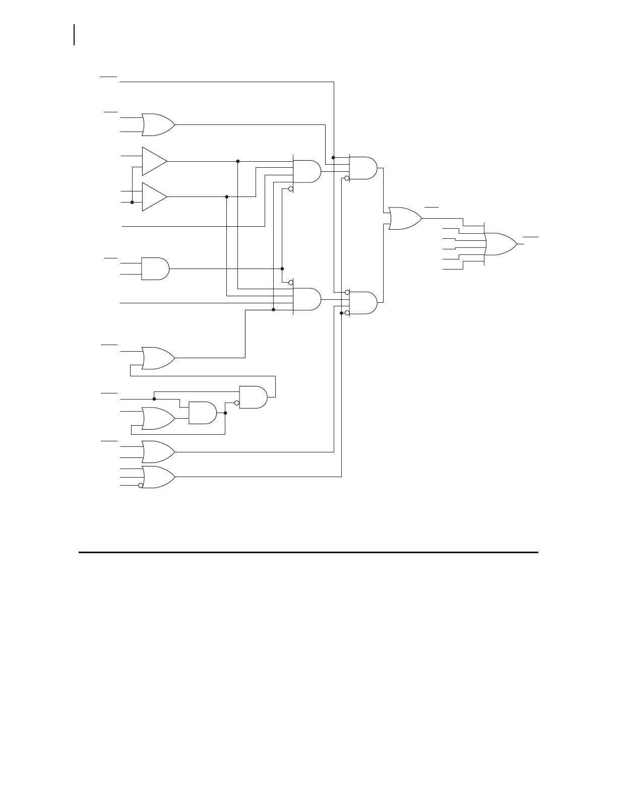
Figure 3.123 Zones 3, 4, and 5 Mho Ground-Distance Element Logic Diagram
Quadrilateral Ground-Distance Elements
The relay has five independent zones of quadrilateral ground distance
protection. The quadrilateral ground distance protection only operates for
single phase-to-ground faults.
Set the reactance (XG) and resistive (RG) reach for each zone independently.
Rather than 90 degrees (purely reactive), the reactance measurement lies along
the setting Z1ANG (complex).
Zone 1 and Zone 2 distance elements are forward only, while you can set
Zones 3–5 distance elements either forward or reverse.
You select whether the quadrilateral ground-distance elements use negative-
or zero-sequence current to polarize the reactance line when the Advanced
Settings are enabled (setting EADVS := Y); otherwise, negative-sequence
current is the default setting.
32SPOF
DIRn := F
MAGn
MBGn
ZnG
MCGn
XAGn
XBGn
XCGn
32GF
OSBn
OSBA
FSA
SPO
SPOA
32GR
32SPOR
3PO
ILOP
VPOLV
mAGF is the Forward A-Phase-to-Ground Mho Distance
Calculation.
mAGR is the Reverse A-Phase-to-Ground Distance
Calculation.
Zone 3, 4, and 5 Mho Ground Distance Logic for
A-Phase. B- and C-Phase Logic Is Similar.
n = 3, 4, or 5
Setting
Relay
Word
Bit
Relay
Word
Bits
Relay
Word
Bit
Relay
Word
Bit
Relay
Word
Bits
Relay
Word
Bits
Relay
Word
Bits
—
+
—
+
IAL
IGL
mAGF < ZnMG
mAGR > —ZnMG
0.1 • I
nom