P.12.7
Date Code 20151029 Protection Manual SEL-411L Relay
Bay Control
Disconnect Logic
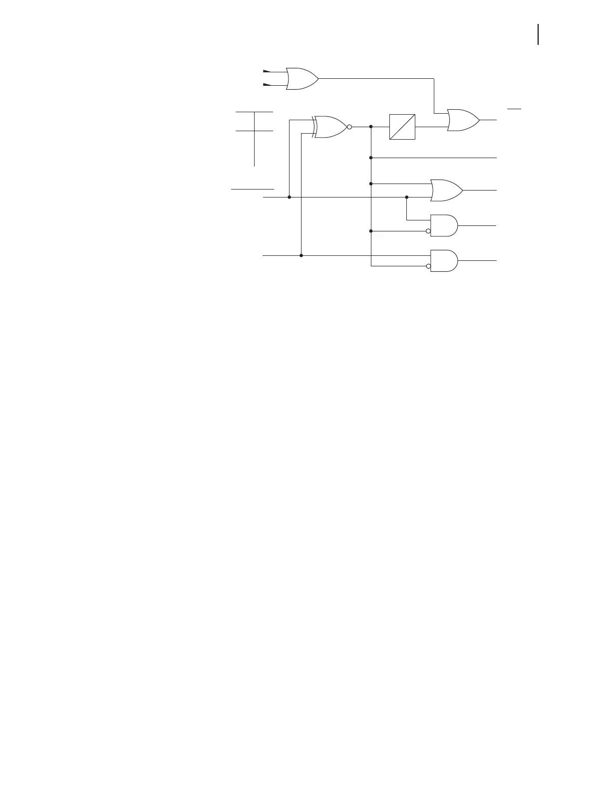
Figure 12.3 Disconnect Switch Status and Alarm Logic
Disconnect Switch Status and Alarm Logic Inputs
89AMm, 89BMm
The 89AMm and 89BMm SELOGIC control equations represent the normally
open and normally closed disconnect switch auxiliary contacts. Typically,
these are set to relay inputs that are wired to the auxiliary contacts.
89CIMm, 89OIMm
If the close or open immobility timer expires, 89CIMm or 89OIMm asserts.
Expiration of the immobility timer indicates that the disconnect failed to move
a minimum distance to open the normally closed auxiliary contact 89BMm
(open to close operation) or to open the normally open auxiliary contact
89AMm (close to open operation).
Disconnect Switch Status and Alarm Logic Settings
89ALPm
This setting in the Bay settings class defines the disconnect switch alarm time.
Disconnect Switch Status and Alarm Logic Outputs
89ALm
If a disconnect switch operation initiated from the front panel does not
complete, the 89ALPm timer expires and the 89ALm Relay Word bit asserts.
Expiration of the 89ALPm timer indicates that an initiated disconnect
operation failed to complete and the disconnect switch is in an undetermined
state. In addition, the 89CSTm or 89OSTm timer deasserts the output signal
(89CLSm or89OPEm) when expired, thus ensuring that there is not a constant
signal applied to the disconnect.
89OIPm
When Relay Word bit 89OIPm asserts, a disconnect switch operation is in
progress. Relay Word bit 89OIP asserts when the states of the 89BMm and
89AMm Relay Word bits are the same, i.e., both asserted or both deasserted.
89CLBm
This Relay Word bit is used for bus zone protection and asserts when the
disconnect is no longer open (89BMm deasserted).
Relay
Word
Bits
89ALPm
0
89CIMm
89OIMm
89ALm
89AMm
89BMm
Disconnect
Alarm Timer
Xnor Logic
Table
Input
AB
Output
00
01
10
11
1
0
0
1
89OIPm
89CLBm
89CLm
89OPNm
SEL
OGIC
Control Equation