P.1.15
Date Code 20151029 Protection Manual SEL-411L Relay
Introduction and Specifications
Specifications
Differential Communications Ports
Fiber Optics—ST Connector
1550 nm single-mode
Tx Power: –18 dBm
Rx Min. Sensitivity: –58 dBm
Rx Max. Sensitivity: 0 dBm
System Gain: 40 dB
Distance Limitations: 120 km
1300 nm multimode or single-mode
Tx Power: –18 dBm
Rx Min. Sensitivity: –58 dBm
Rx Max. Sensitivity: 0 dBm
System Gain: 40 dB
Distance Limitations: x km
where: x = 30 for multimode
x = 80 for single mode
1300 single mode (C37.94 modulated):
Tx Power: –24 dBm
Rx Min. Sensitivity: –37.8 dBm
Rx Max. Sensitivity: 0 dBm
System Gain: 13.8 dB
Distance Limitations: 15 km
850 nm multimode, C37.94
Tx Power: 50 µm: –23 dBm; 62.5 µm: –19 dBm
Rx Min. Sensitivity: 50 µm: –32 dBm; 62.5 µm: –32 dBm
Rx Max. Sensitivity: 50 µm: –11 dBm; 62.5 µm: –11 dBm
System Gain: 50 µm: 9 dB; 62.5 µm: 13 dB
Distance Limitations: 2 km
Electrical
EIA-422: 64 kbps synchronous;
Isolated to 1500 Vac
CCITT G.703: 64 kbps synchronous, codirectional
Time Inputs
IRIG-B Input—Serial Port 1
Input: Demodulated IRIG-B
Rated I/O Voltage: 5 Vdc
Operating Voltage Range: 0–8 Vdc
Logic High Threshold: 2.8 Vdc
Logic Low Threshold: 0.8 Vdc
Input Impedance: 2.5 k
IRIG-B Input—BNC Connector
Input: Demodulated IRIG-B
Rated I/O Voltage: 5 Vdc
Operating Voltage Range: 0–8 Vdc
Logic High Threshold: 2.2 Vdc
Logic Low Threshold: 0.8 Vdc
Input Impedance: 50 or > 1 k
Dielectric Test Voltage: 0.5 kVac
Operating Temperature
–40° to +85°C (–40° to +185°F)
Note: LCD contrast impaired for temperatures below –20° and
above +70°C
Humidity
5% to 95% without condensation
Weight (Maximum)
4U Rack Unit:
5U Rack Unit:
6U Rack Unit:
9.5 kg (21 lbs)
11.8 kg (26 lbs)
13.6 kg (30 lbs)
Terminal Connections
Rear Screw-Terminal Tightening Torque, #8 Ring Lug
Minimum:
Maximum:
1.0 Nm (9 in-lb)
2.0 Nm (18 in-lb)
User terminals and stranded copper wire should have a minimum
temperature rating of 105°C. Ring terminals are recommended.
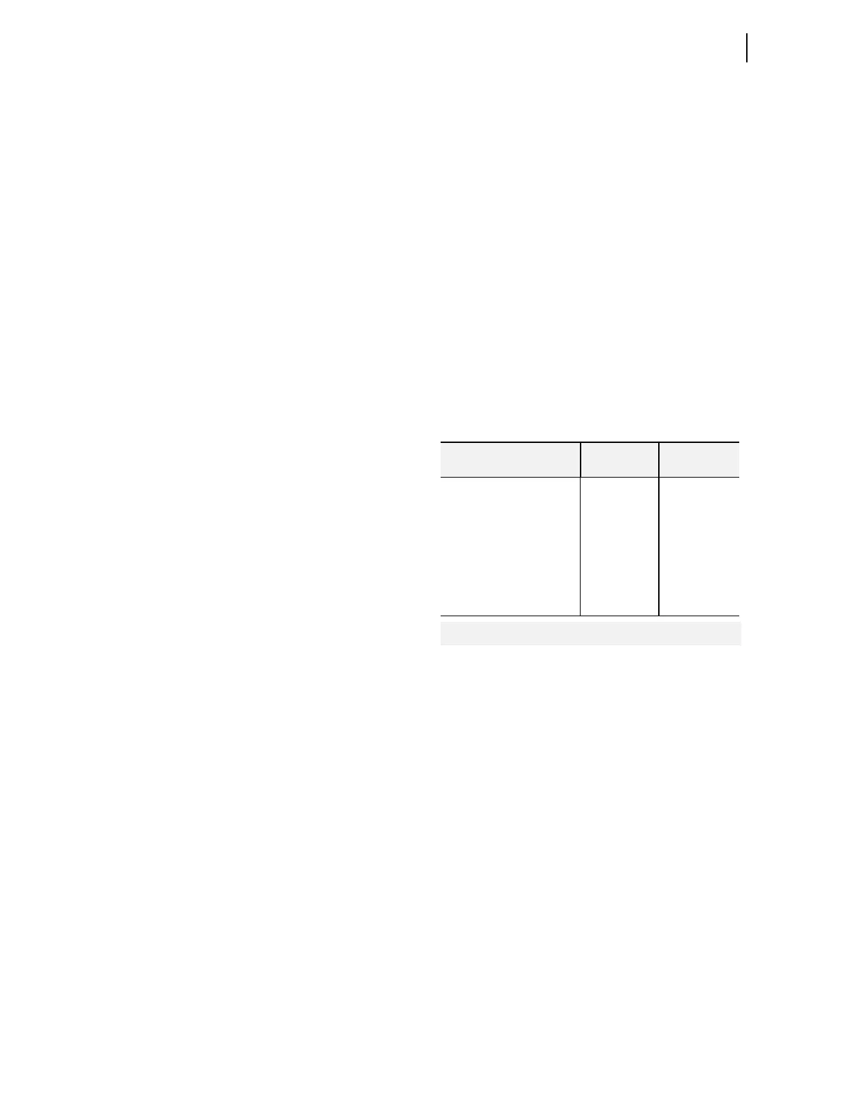
Wire Sizes and Insulation
Wire sizes for grounding (earthing), current, voltage, and contact
connections are dictated by the terminal blocks and expected load
currents. You can use the following table as a guide in selecting
wire sizes:
Type Tests
Electromagnetic Compatibility (EMC)
Emissions: IEC 60255-25:2000, Class A
Electromagnetic Compatibility Immunity
Conducted RFI
Immunity:
IEC 60255-22-6:2001, 10 Vrms
IEC 61000-4-6:2008, 10 Vrms
Digital Radio
Telephone RF:
ENV 50204:1995, 10 V/m at 900 MHz
and 1.89 GHz
Electrostatic Discharge
Immunity:
IEC 60255-22-2:2008
IEC 61000-4-2:2008
Levels 2, 4, 6, and 8 kV contact;
Levels 2, 4, 8, and 15 kV air
IEEE C37.90.3-2001,
Levels 2, 4, 6, and 8 kV contact;
Levels 2, 4, 8, and 15 kV air
Electrical Fast Transient
Burst Immunity:
IEC 61000-4-4:2011,
IEC 60255-22-4:2008,
4 kVat 5 kHz; 2 kV at 5 kHz
on Comm Ports
Power Frequency
Magnetic Field
Immunity:
IEC 61000-4-8:2009
1000 A/m for 3 s
100 A/m for 60 s
Pulse Magnetic Field
Immunity:
IEC 61000-4-9:2001
1000 A/m
Damped Oscillatory
Magnetic Field:
IEC 61000-4-10:2001
Severity Level: 100 A/m
Connection Type
Minimum
Wire Size
Maximum
Wire Size
Grounding (Earthing)
Connection
18 AWG
(0.8 mm
2
)
14 AWG
(2.5 mm
2
)
Current Connection 16 AWG
(1.5 mm
2
)
12 AWG
(4 mm
2
)
Potential (Voltage)
Connection
18 AWG
(0.8 mm
2
)
14 AWG
(2.5 mm
2
)
Contact I/O 18 AWG
(0.8 mm
2
)
14 AWG
(2.5 mm
2
)
Other Connection 18 AWG
(0.8 mm
2
)
14 AWG
(2.5 mm
2
)