P.11.18
SEL-411L Relay Protection Manual Date Code 20151029
Testing and Troubleshooting
Test Methods
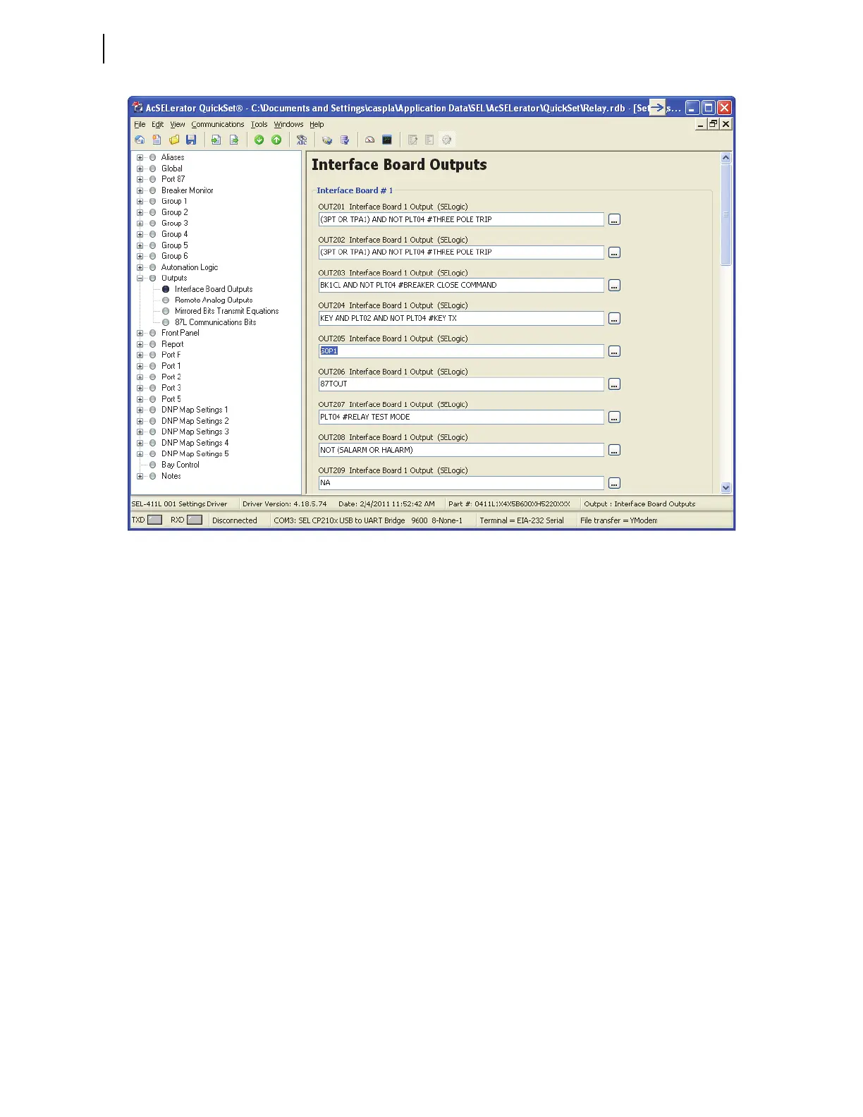
Figure 11.8 Setting I/O Board #1 Outputs: ACSELERATOR QuickSet
Step 3. Set OUT205 to respond to the 50P1 element pickup.
a. Move the cursor to the OUT205 Interface Board 1
Output (SEL
OGIC) text box and double-click the left
(regular) mouse button.
b. Delete the NA default setting.
c. Type 50P1.
d. Press <Tab> or click in any other text box.
e. The relay checks the validity of the setting you entered.
An invalid setting (you could have mistyped the
element name) causes the OUT205 text box to turn red.
If the setting is valid, the text box displays the new
setting on a white background.
Step 4. Click File > Save to save the new settings in
ACSELERATOR
QuickSet.
Step 5. Upload the new settings to the relay.
a. Click File > Send.
ACSELERATOR QuickSet prompts you for the settings
class you want to send to the relay, as shown in the
Group Select dialog box in Figure 11.9.
b. Click the Output check box.
c. Click OK.
The relay responds with the Transfer Status dialog
box in Figure 11.9.