09/03
2-76
DC 3535/2240/1632, WC M24
4-640
Initial issue
Status Indicator RAPs
4-640 Belt Walk failure
This hidden fault is declared if the dynamic (short term) color-to-color registration exceeds
specification while image formation is in progress.
Initial Actions
Adjust the color registration (ADJ 9.6). If the problem remains, continue with the procedure.
Procedure
Switch on the power. Enter dC330 [004-014] and press Start. Measure voltage between P/
J533-A11(+) on the I/F PWB and GND(-). Between +3 VDC and +1 VDC is measured.
YN
There is +5 VDC between P/J533-A9(+) and P/J533-A10(-) on the I/F PWB.
YN
Close the Front Cover. If the voltage between P/J533-A9(+) P/J533-A10(-) is less
than +5VDC, replace the MCU PWB (PL 13.1).
There is +5 VDC between P/J533-A11(+) on the I/F PWB and GND(-).
YN
0 VDC is measured between P/J533-A11(+) on the I/F PWB and GND(-).
YN
Refer to Figure 1. Check the wires from J533 on the I/F PWB to J119 on the IBT
Edge Sensor for damage or loose connections. If the wires are OK, replace the
IBT Edge Sensor (PL 5.4)
If the problem continues, replace the MCU PWB (PL 13.1).
Refer to Figure 1. Check the wires from J533 on the I/F PWB to J119 on the IBT
Edge Sensor for a short circuit. If the wires are OK, replace the IBT Edge Sensor (PL
5.4).
Refer to Figure 1. Check the wires from J533 on the I/F PWB to J119 on the IBT Edge
Sensor for an open circuit. If the wires are OK, replace the IBT Edge Sensor (PL 5.4).
+24 VDC is measured between P/J550-5(+) on the I/F PWB and GND(-).
YN
Go to the +24 VDC Wirenets and check +24VDC circuit up to P/J550-5 on the I/F PWB.
Remove the IBT Assembly. Enter dC330 [004-001] and press Start. The Steering Motor
energized.
YN
Refer to Figure 2. Check the wires from P550 on the I/F PWB to J207 on the IBT Steering
Motor for damage or a loose connection. If the wires are OK, replace the MCU PWB (PL
13.1). If the problem continues, replace the I/F PWB (PL 9.1), and IBT Steering Motor (PL
1.3).
Check the IBT Belt installation (REP 9.22). If no problems are found, replace the IBT Assembly
(PL 5.2).
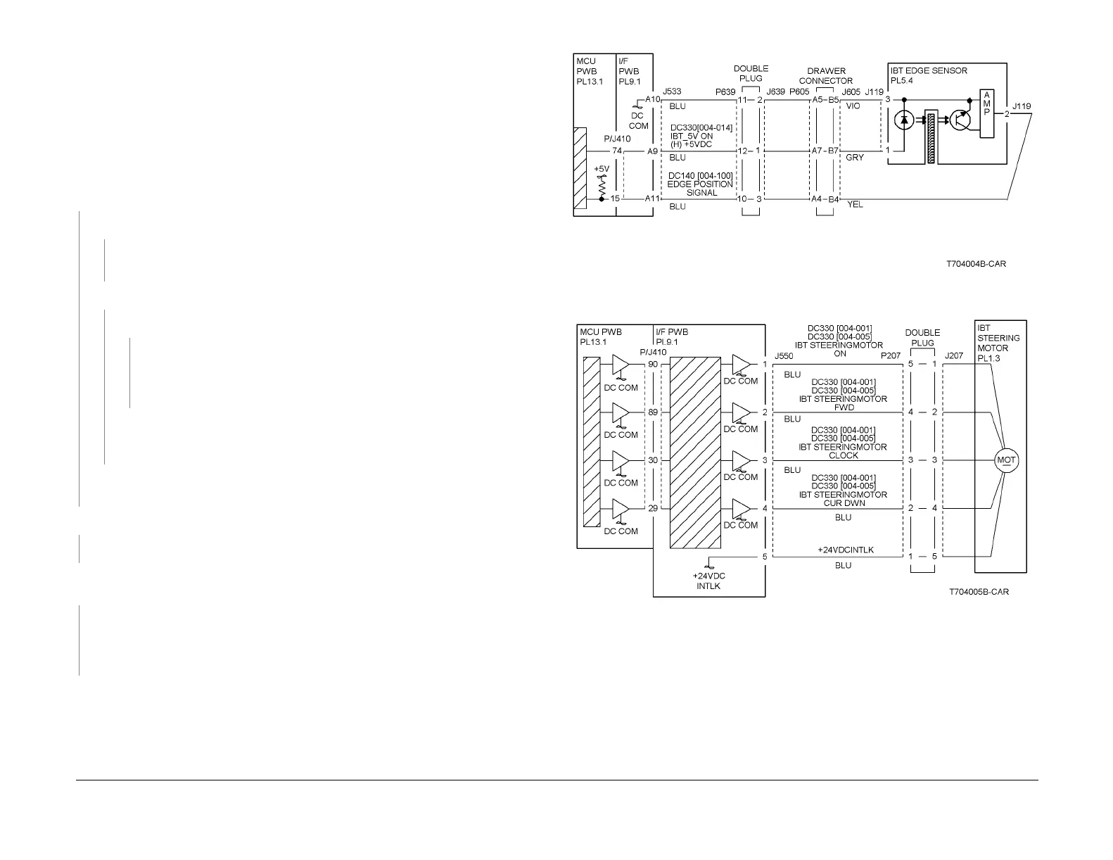
Figure 1 4-640 RAP Circuit Diagram - Belt Edge Sensor
Figure 2 4-640 RAP Circuit Diagram - IBT Steering Motor

 Loading...


