09/03
2-280
DC 3535/2240/1632, WC M24
12-305
Initial issue
Status Indicator RAPs
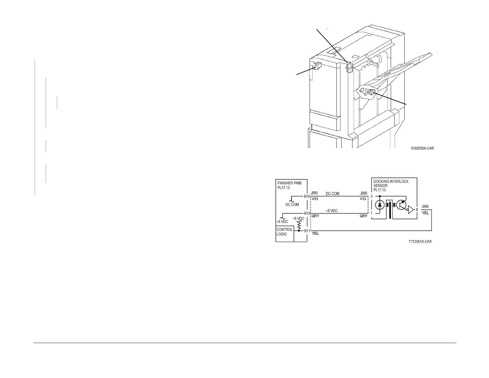
12-305 Docking Interlock Open
The Docking Interlock is open.
Procedure
Block the Docking Interlock Sensor with a sheet of paper (Figure 1). 012-305 is cleared.
YN
+5 VDC is measured between the Docking Interlock Sensor P/J866-1 and -3 (Figure
2).
YN
Disconnect Finisher PWB P/J850. +5 VDC is measured between Finisher PWB
P850-B10 and -B12.
YN
Replace the Finisher PWB (PL 17.13) (Figure 3).
Repair the open circuit between Finisher PWB J850-B10 and -B12 and Docking
Interlock Sensor J866-1 and -3.
+5 VDC is measured between Finisher PWB P/J850-B11 and ground.
YN
Replace the Finisher PWB (PL 17.13)
+5 VDC is measure between Docking Interlock Sensor P/J866-2 and ground.
YN
Check the wire between the Docking Interlock Sensor P/J866-2 and the Finisher
PWB P/J850-A2 for an open circuit or poor contact.
Replace the Docking Interlock Sensor (PL 17.13).
Mismatching between the Actuator and the Docking Interlock Sensor. Check the Sensor for
improper installation, the Actuator for breakage and bending, and the Finisher and the Main
Processor for the docking failure.
Figure 1 Component Location
Figure 2 12-305 RAP Circuit Diagram - Docking Interlock Sensor
Docking
Interlock
Sensor
(rear)
Front Door
Interlock
Switch
Top Cover
Interlock
Switch

 Loading...


