09/03
4-44
DC 3535/2240/1632, WC M24
REP 6.5
Initial issue
Repairs and Adjustments
REP 6.5 IIT/IPS PWB
Parts List on PL 18.3
Removal
1. Gather all available settings information. This includes the machine NVM log, the
Machine Settings floppy disk, copies of the Configuration Report, etc. If possible save the
current Machine Settings to the floppy.
WARNING
To avoid personal injury or shock, do not perform repair or adjustment activities with
the power switch on or electrical power applied to the machine.
CAUTION
PWBs can be damaged by electrostatic discharge. Observe all ESD procedures.
2. Remove the Platen Glass (REP 6.2).
3. Remove the IPS Cover (PL 18.3).
a. Manually move the Full Rate Carriage (PL 18.6) toward the left.
b. Remove front screws (2), left screws (2), and right screws (2) from IPS Cover (PL
18.3).
c. Loosen rear screw and remove cover.
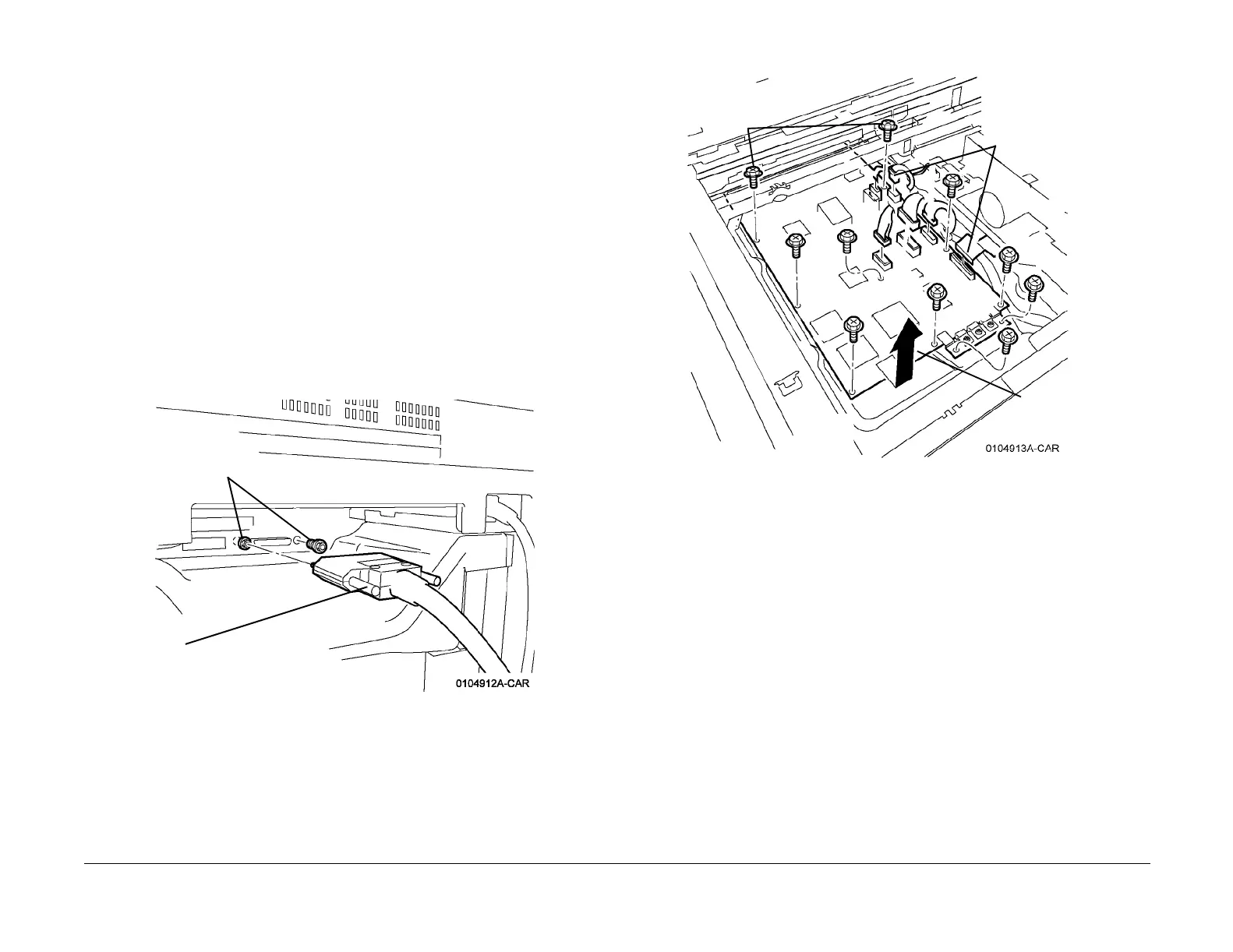
4. Disconnect IOT/IIT Cable and remove Screws from IIT (Figure 1).
Figure 1 Disconnecting Cable and Removing Screws from IIT
5. Remove IIT/IPS PWB (Figure 2).
Figure 2 Removing IIT/IPS PWB
Replacement
1. Install the new IIT/IPS PWB. Switch on the power and connect the PWS.
2. Check the IIT/IISS software version to ensure that it matches the system software config-
uration. Refer to the Software Configuration table in the system software upgrade instruc-
tions contained on the S/W update CD. If the version does not match, reload the software
in accordance with the instructions on the CD.
3. If a good Machine Settings floppy is available, exit, then reenter the PWS Tool. Select
Read from Floppy when starting the tool. If no floppy is available, or if the data on the
existing floppy is questionable, go to step 5.
4. Go to dC351 and select Restore Machine Settings. After completion, go to step 7.
5. If a good Machine Settings floppy is not available, or if the data on the existing floppy is
questionable, go to dC351. In the Special Batch Write area, select the appropriate market
region, then press the Batch Write NVM button.
6. Using the resources gathered in step 1 of the removal procedure, reenter NVM data to
restore the machine configuration.
7. Ensure that the customer settings are correct. Contact the customer’s system administra-
tor to configure, if necessary.
8. Perform the IIT Calibration (ADJ 9.7).
9. Go to dC351 and select Save Machine Settings. Save the settings to floppy disk per the
procedure.
1
Loosen Connector Screws
and Disconnect Plug
2
Remove
screw studs
(2)
1
Remove screws
(10)
2
Disconnect
connectors (6)
3
Remove
PWB

 Loading...


